Welding and cutting recommendations
for Toolox®
TOOLOX® GRADES ARE ENGINEERING AND TOOL STEELS THAT ARE DESIGNED FOR FAVORABLE WELDABILITY AND CUTTING CHARACTERISTICS.
The following welding and cutting recommendations are presented in order to support the full potential of welded structures of Toolox®. As for all types of engineering and tool steels the level of requirements increases with increased hardness of the steel. This means for instance that Toolox® 44 is fully weldable but it is necessary to strictly follow our recommendations
Any conventional welding and cutting method can be used for these steels and they can be welded to other kinds of weldable steels.
Toolox® is available as plates and round bars. All types of products of these steels are addressed in this context. References are made to our TechSupports documents and WeldCalc™ which give further information regarding a certain topic. Each TechSupport addresses further information in a given area such as suitable consumables for welding of Toolox®.
The software WeldCalc allows users to further optimize the welding performance with respect to a certain welding situation.
TechSupports can be found on www.ssab.com/download.
A user licence for WeldCalc can be attained through registration on the same home page. Both TechSupports and WeldCalc are free of charge.
Welding recommendations
JOINT PREPARATION
Joint preparations can be made with all conventional methods such as thermal cutting, machining and grinding pins. If thermal cutting is applied a thin oxide or nitride layer will be present that is approximately up to 0.2 mm thick. This layer is to be removed before welding, usually by grinding. Recommendations for thermal cutting are specified under a separate headline.
In addition, shearing and punching is feasible for plate thicknesses up to about 10 mm.
Prior to each weld pass it is essential that the joint preparation area should be clean from contaminations such as moisture, grease, rust and oil.
SELECTION OF WELDING CONSUMABLES
Stainless, unalloyed and low-alloyed types of consumables are suitable. For welded structures subjected to moderate stresses, the stainless types typically give the best properties and are generally to prefer in these cases. This is especially the case for welding of Toolox® 44.
For structures where the joints are exposed to high stress loads low-alloyed consumables is the best option.
Essential aspects when selecting consumables are found below. In addition, TechSupport no 60 addresses examples of different brand names of consumables as well as it gives more detailed information about selection of consumables.
Stainless consumables
All Toolox® steels can be welded with stainless austenitic steel consumables of type AWS 307 or AWS 309. These classification designations are valid for consumables of all conventional welding methods.
After welding, an even higher resistance is achieved to hydrogen cracks in the joint in relation to unalloyed and low-alloyed consumables. The microstructure of the all weld metal normally results in a high toughness where its’ yield strength is around 500 MPa. Due to the high resistance to hydrogen cracks no restriction applies of their hydrogen content.
Other important benefits of welding with this type of consumables are:
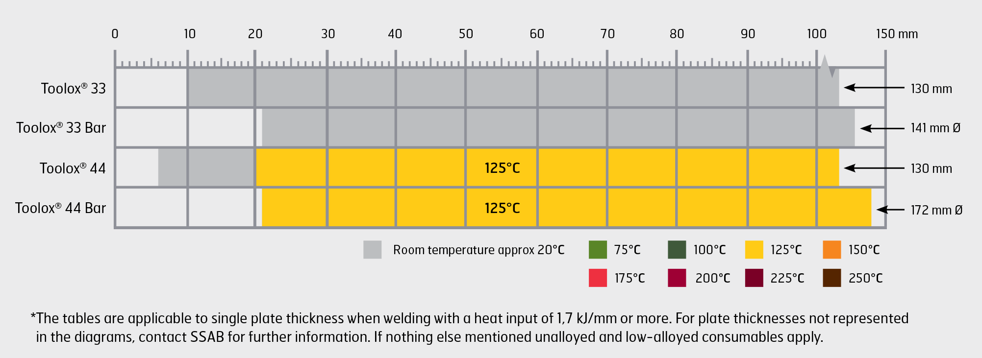
- Preheat/Interpass temperatures, which means a temperature above +20 °C in the joint as well as in the surrounding air, can be avoided for all products of Toolox® 33. Toolox® 44 is to be welded with preheating according to the table below.
- Welding operations can be performed for the welding to other kinds of steels than of unalloyed- and low alloyed types, such as:
- Stainless steels
- Manganese steels (Hadfield steel)
In this case apply welding conditions that suits both the Toolox® grade and the other type of steel to be welded.
The first preference is consumables according to type AWS 307. The main difference between them is that the resistance of hot cracking is somewhat higher when using consumables of type AWS 307 compared to type AWS 309.
Drawbacks with the stated stainless consumable are that:
- Gas cutting on welded joints can not be performed. However both plasma and laser cutting is feasible in this case. If gas cutting is requested in this situation, apply unalloyed or a low-alloyed consumables. The weld metal that is produced by the last mentioned consum-ables can be cut with all thermal cutting methods.
- The consumables are more expensive compared to unalloyed and low-alloyed versions.
Unalloyed and low-alloyed consumables
Unalloyed and low-alloyed consumables should meet the specified strength criteria, and their hydrogen contents ought to be sufficiently low.
Suitable consumables are available within a wide range of strengths. In most types of applications this means types with yield strengths in the all weld metal up to about 930 MPa.
t is often beneficial to apply a low strength consumable with yield strengths of approximately 500 MPa. The reasons are that:
- The resistance to hydrogen cracks in joints is increased even further
- A higher toughness in the weld metal is often supported by a consumable with lowered strength
Low-alloyed consumables with yield strengths up to approximately 930 MPa is feasible and they can be applied for welding of Toolox®. These consumables can attain beneficial toughness in the weld metal that can meet the required toughness of the Toolox® grades.
For the highest possible hardness in the weld metal, it is possible to weld Toolox® with consumables especially designed for welding of engineering and tool steels. These consumables can attain a very high hardness in the weld metal. However beneficial toughness of the weld metal is typically not emphasized for these products. Contact SSAB for further information regarding selection of this kind of consumables.
For all types of unalloyed and low-alloyed consumables the hydrogen criteria is set to a maximum of 5 ml hydrogen/100 g of weld metal in order to avoid hydrogen cracks in the joint. There are consumables for all welding methods that can fulfill this requirement.
All solid wires at MAG, TIG and plasma welding can meet the hydrogen criteria.
Consumables that utilize a flux or a coating have an addi-tional source for moisture pickup. The categories of con-sumables that can reach sufficiently low levels of hydrogen are mentioned in the table below. This information serves as a general guide for selecting consumables. Information regarding the hydrogen potential for a specific consumable can be provided by its’ manufacturer.
| Consumables that have the potential to reach suffciently low hydrogen content for welding of Toolox@ grades |
| Unalloyed and low-alloyed consumables |
Type of consumables |
| Solid wires (MAG- and TIG-welding) |
All types |
| Flux cored wires (MAG) |
Basic and rutile variants |
| Metal cored wires (MAG) |
Certain types. See the data sheet for the consumables |
| Consumables for MMA-welding |
Basic variants |
| Consumables for SAW |
Basic flux/solid wire combinations |
| Welding consumables, EN class |
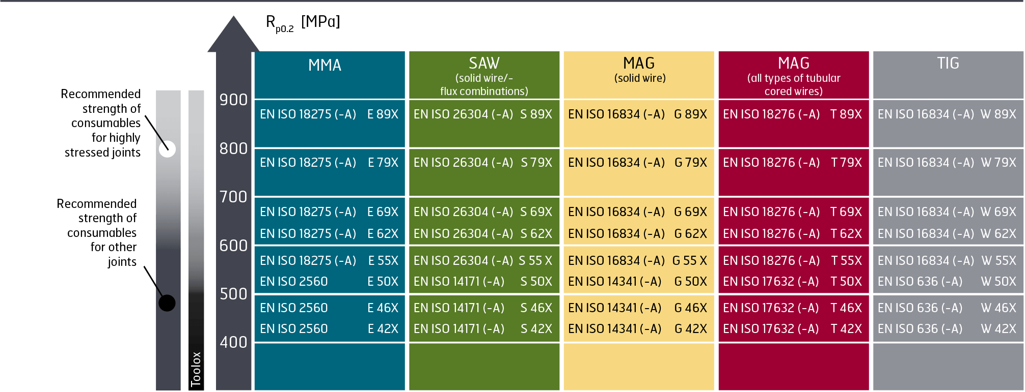 |
| Welding consumables, AWS class |
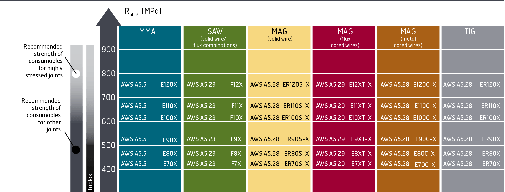 |
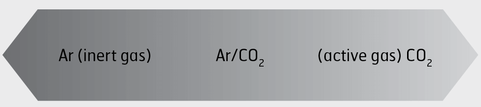
SHIELDING GAS
For welding methods that applies shielding gas, the choice and mixture of the gases is dependent on the welding situation. Mixtures of argon (Ar) and carbon dioxide (CO2) are the most commonly used.
In all welding methods based on shielding gas, the flow of shielding gas depends on the welding situation. A too low gas flow can lead to an insufficient gas protection of the melt. Excessive gas flow can become turbulent thus deteriorating the gas protection. A general guideline is that the shielding gas flow measured in l/min is set to the same value as the inner diameter of the torch nozzle measured in mm.
| Welding consumables, AWS class |
- Facilitates striking of the arc
- Reduced spatter
- Low amount of oxides
|
 |
- Stable arc
- Low porosity
- More weld spatter/clogging of the welding nozzle
- High penetration of the weld metal
|
| Examples of shielding gas mixtures |
| Welding method |
Arch type |
Position |
Shelding gas |
| MAG, solid wire |
Short Arc |
All positions |
18-25% CO2 rest. Ar |
| MAG, cored wire |
Short Arc |
All positions |
18-25% CO2 rest. Ar |
| MAG, solid wire |
Short Arc |
Horizontal (PA, PB, PC) |
15-20% CO2 rest. Ar |
| MAG, FCAW |
Spray Arc |
All positions |
15-20% CO2 rest. Ar |
| MAG, MCAW |
Spray Arc |
Horizontal (PA, PB, PC) |
15-20% CO2 rest. Ar |
| Robotic and automated MAG |
Spray Arc |
Horizontal (PA, PB, PC) |
8-18% CO2 rest. Ar |
| TIG |
Spray Arc |
All positions |
100% Ar |
HEAT INPUT
The heat input from a welding performance describes the delivered energy/length to the joint. The level of heat input affects the mechanical properties of the joint. The heat input depends on the applied welding method as well as the levels of current, voltage and the travel speed of the welding process.
During welding, energy will be lost in the arc. The thermal efficiency factor (k) expresses the part of the heat input that is transferred to the joint. Different methods of welding have varying thermal efficiency factors in accordance with below. See below for approximate values of k and how the heat input is calculated.
If special requests regarding certain mechanical properties in the joints of Toolox®, contact SSAB for further assistance regarding selection of heat input.
| The heat input can be calculated using the formula below |
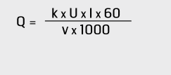 |
Q = Heat input [kJ/mm]
U = Voltage [V]
I = Current [A]
v = Welding speed [mm/min]
k = Thermal efficiency
[dimensionless] |
| Welding method |
Thermal effciency k [dimensionless] |
| MMA |
0.8 |
| MAG, all types |
0.8 |
| SAW |
1.0 |
| TIG |
0.6 |
| General effects of heat input on a welded joint |
- Better toughness
- Increased strength
- Reduced deformation
- Lower residual stresses
- Narrower HAZ
|
 |
- Higher productivity
for conventional
welding methods
|
Avoidance of hydrogen cracks
During welding hydrogen cracks can form in different types of steels but they are emphasized for all types of high strength steels, including Toolox®. The risk for this type of crack is minimized by following the recommendations in this brochure.
From a steel point of view the resistance is related to the chemical composition of the steel. In general the less level of alloys, the higher is the resistance to hydrogen cracks. Increasing levels of alloys are in general terms added in order to attain:
- Increased hardness and strength of the steel
- Uniform mechanical properties throughout the thickness of the plate
The influence from the alloy content can be expressed by the carbon equivalent for the steel. The carbon equivalent is usually expressed as CEV or CET in accordance with the equations below. The lower the carbon equivalent it is; the higher is the resistance to hydrogen cracks in the steel.
Typical and max levels for carbon equivalents are given in our product data sheet for each Toolox® grade and they also depend of the plate thickness/diameter of the steel grade. However, there is no need to calculate the carbon equivalent in order to follow our welding recommendations presented in this brochure.
In the following tables the carbon equivalents for the Toolox® grades are compared with some commonly used products for tooling and machined components.
Toolox® steels typically have substantially lower carbon equivalent values compared to other tool & engineering steels with comparable hardness levels. As a consequence, the overall weldability of Toolox® is significantly higher in relation to other tool/machine steels.
| Carbon equivalents for Toolox® 33 in relation to other tool/machine steels with similar hardness levels |
| Steel |
CET [%], typcial values |
CEV [%], Typcial values |
| Toolox® 33 |
0.38–0.42 |
0.63–0.71 |
| AISI: 4140 / EN: 42CrMo4 |
1.13 |
1.27 |
| AISI: 4340 / EN: 34CrNiMo6 |
0.58 |
0.85 |
| AISI: 1045 / EN: C45 |
0.52 |
0.57 |
| Carbon equivalents for Toolox® 44 in relation to other tool/machine steels with similar hardness levels |
| Steel |
CET [%], typcial values |
CEV [%], Typcial values |
| Toolox® 44 |
0.57 |
0.96 |
| AISI: H13 / EN: 1.2344 |
0.83 |
1.89 |
| Two rules for avoidance of hydrogen cracks |
|
1) Minimize the hydrogen content in and around the joint:
- When required, apply the right preheat and interpass temperature of the joint
- Use welding consumables with a sufficiently low hydrogen content that is in accordance with the recommendations from SSAB
- Keep impurities out of the weld area
|
1) Keep the stress levels in and around the joint at sufficiently low levels:
- Prepare the joint with a small minimum gap width
- Arrange the weld sequences so that residual stresses are minimized
- Do not use consumables of higher strengths than necessary
|
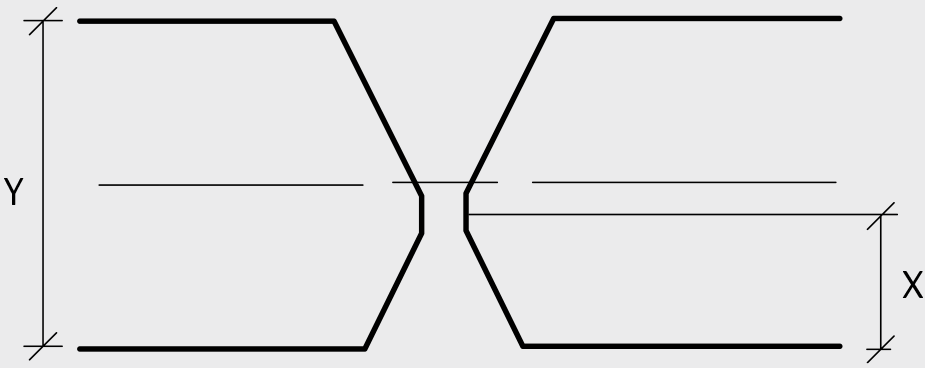
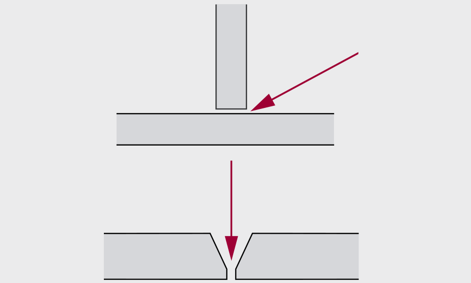
Joint geometry
When Toolox® is welded through the midsection of the plate thickness, asymmetrical joints is recommended for plate thicknesses/diameters above 25 mm. This will give additional resistance to hydrogen cracks for the first root passes. The reasons are that:
-The center part of the plate may, to some extent, contain chemical elements that can support formation of this kind of crack. The larger the plate/bar thickness it is, the more pronounced will this matter be.
- The root passes are more sensitive to hydrogen cracks
Joints with plate thicknesses/diameters up to 25 mm can either be symmetrical or asymmetrical.
Large root gaps in joints supports higher stress concen-trations which reduces the resistance to hydrogen cracks. SSAB recommends that the size of the root gap is set to maximum 3 mm in order to reduce stress concentrations.
Welding sequences
Start and stop sequences from welding are preferably made approximately 50—100 mm away from corners of a joint in order to avoid excessive amounts of residual stresses in the joint.
| Joints with plate thicknesses above 25 mm |
|
Asymmetrical joint: The center of the joint is preferably taken approximately 5 mm from the center of the plate thickness
 |
|
Y: Plate thickness
|
X: (Plate thickness/2)-5 mm
|
| Maximum gap 3 mm |
 |
| Welding sequences |
 |
Preheat recommendations
Preheating is necessary in many cases in order to minimize the risk for hydrogen cracks. Preheating facilitates a more rapid movement of hydrogen out from the joint. It is essen-tial that the requested preheat temperatures are followed and that the procedure is carried out in an accurate way. It is essential that preheating, when required, is also applied on tack welds. Each of the tack welds shall be preferably be at least 50 mm long. Contact SSAB for further information if tack welds below 50 mm are requested.
The necessity of preheating differs between welding with unalloyed and low-alloyed verses welding with stainless consumables.
- When a joint consist of different plate thicknesses/bar diameter of the same Toolox® grade, the thickest plate thickness/diameter determines the minimum required preheat and interpass temperature.
- When a Toolox® grade is welded to a different steel grade the plate/bar requiring the highest minimum preheat temperature determines the minimum preheat and interpass temperature.
- When no preheating is stated in the table below, no preheating is necessary for heat inputs in the range of 1.0–1.6 kJ/mm.
The minimum preheat temperature for welding with all types of recommended consumables is raised by 25°C compared to the diagram above for each of the following situations.
- For heat inputs in the range of 1.0–1.6 kJ/mm: When min preheat temperatures above room temperature is stated in the table above.
- For joints with very high levels of restraint.
- For temperatures of below +5°C in the surrounding air and/or in the plates/bars.
- When welding is performed in a very humid climate.
If more than one of the conditions above is present at the same time, contact SSAB for further information.
Minimum preheat temperatures for welding with heat inputs < 1.0 kJ/mm can for example be calculated using the software WeldCalc developed by SSAB or by adopting a relevant standard for this measure.
The maximum preheat temperatures is set to +580°C for all types of welding performances and it applies to all products of Toolox®. It is specified in order to attain beneficial mechanical properties in the joint.
| Single plate thickness |
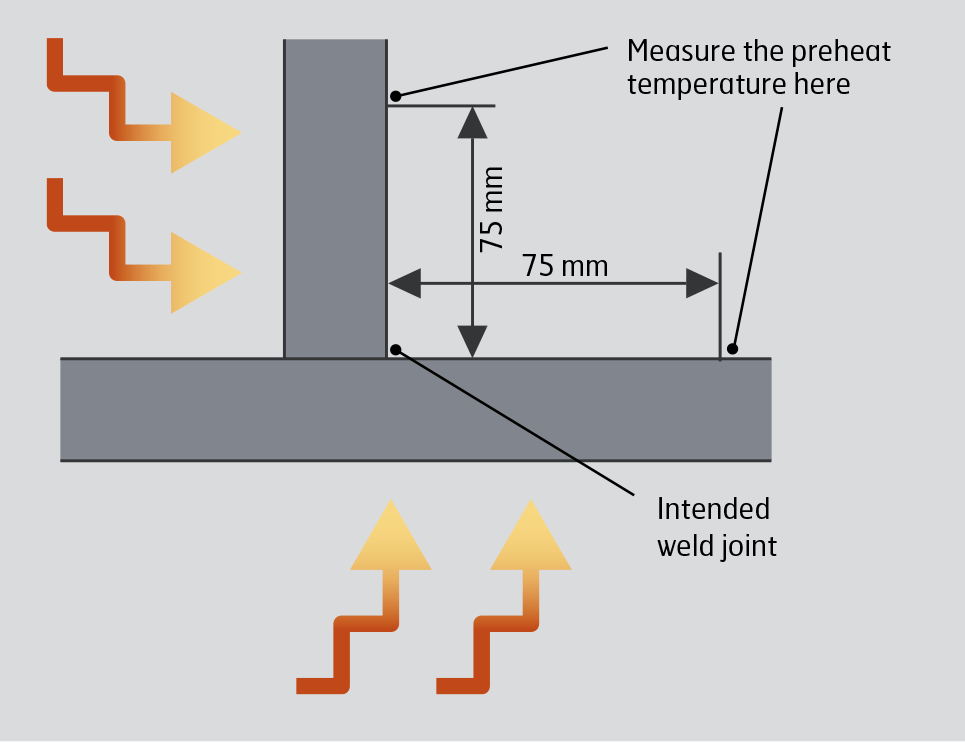 Measure the temperature of the thickest plate in the joint. A waiting time of minimum 2 min/25 mm thickness should be conducted before measuring the preheating temperature. The minimum preheating temperature should be obtained in an area of 75+75 mm around the intended weld joint. Measure the temperature of the thickest plate in the joint. A waiting time of minimum 2 min/25 mm thickness should be conducted before measuring the preheating temperature. The minimum preheating temperature should be obtained in an area of 75+75 mm around the intended weld joint. |
The required preheat and interpass temperatures can be achieved in several ways. Heating furnaces or electrical preheater elements around the prepared joint are often the best since they provide uniform heating of the same area. The temperature should be monitored by using for an example a pyrometer or by a contact thermometer.
| Unalloyed and low-alloyed consumables – minimum preheat and interpass temperatures [°C] |
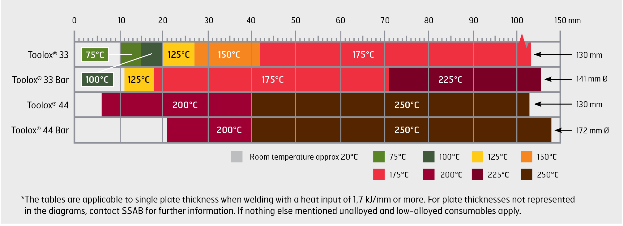 |
| Stainless consumables – minimum preheat and interpass temperatures [°C] |
 |
WELDING ON PRIMED PLATES
The Toolox® grades can be delivered with a primer that counteracts corrosion. Welding can be carried out directly on the primer due to its low zink content. The primer can easily be brushed or grinded away in the area around the joint. Removing the primer prior to welding can minimize the porosity in the weld metal and facilitate welding in other positions other than the horizontal. If the primer is left on the weld preparation, the porosity will be slightly increased. The MAG process with basic types of flux cored wires and the MMA welding process offer the lowest amount of porosity. As in all welding operations good ventilation must be maintained to avoid a harmful effect on the welder and his/hers surroundings. Further information in this respect can be found in TechSupport no. 25.
| Steel |
Holding temperature [°C] |
Heating and cooling rate [°C/h] |
Holding time [min/mm*] |
Suitable time at the holding temperature [h] |
| Toolox® 33 |
550–590 |
100 |
2 |
1–6 |
| Toolox® 44 |
540–580 |
100 |
2 |
1–6 |
*Single plate thickness or min/mm of the diameter
WELDING ON PRIMED PLATES
The Toolox® grades can be delivered with a primer that counteracts corrosion. Welding can be carried out directly on the primer due to its low zink content. The primer can easily be brushed or grinded away in the area around the joint. Removing the primer prior to welding can minimize the porosity in the weld metal and facilitate welding in other positions other than the horizontal. If the primer is left on the weld preparation, the porosity will be slightly increased. The MAG process with basic types of flux cored wires and the MMA welding process offer the lowest amount of porosity. As in all welding operations good ventilation must be maintained to avoid a harmful effect on the welder and his/hers surroundings. Further information in this respect can be found in TechSupport no. 25.
WELDING ON PRIMED PLATES
When performing welding procedure qualifications, the steel groupings all Toolox® grades including of their complete plate thickness range belongs to material group 3.2.
WELDING TOOLOX® TO OTHER TYPES OF STEELS
When a Toolox® grade is welded to other types of steels, apply welding conditions that suits all included steels in the joint.
Thermal cutting recommendations
The low level of alloys for the Toolox® grades contributes to their advantageous properties regarding thermal cutting, such as their high resistance to hydrogen cracks due to cutting. In this respect the influence from alloys in the steel is similar between cutting and welding technology. As a result, the beneficial carbon equivalent values of Toolox® lead to increased resistance to hydrogen cracks during thermal cutting. The definition of carbon equivalents is described in the welding recommendations under the head line: Avoidance of hydrogen cracks.
The inherent high toughness of the Toolox® grades further lowers the risk for defects produced during thermal cutting. In industrial practice this makes it possible to produce non square shapes in a much more productive way than the typically extensive machining of other types of tool and machine steels.
All methods for thermal cutting can be performed for all products of Toolox®. Thermal cutting can be performed with the same procedure and parameters as for cutting of mild steels except that:
- For gas and plasma cutting measures are to be taken in order to avoid hydrogen cracks in and around the cut edge. Plasma cutting is only to be performed with oxygen as a plasma gas in order to optimize the cut edge quality. If a secondary gas is applied there are less restrictions in the seleted gas chemistry. Air or pure oxygen is both suitable and are the most common types.
- Postheating of the cut edge is recommended in order to attain optimized machinability in a thermally cut edge. In addition, postheating increases the resistance to hydrogen cracks in the cut edge. Postheating is preferable for gas cutting but typically not necessary for plasma or laser cutting.
The principal reasons for formation of hydrogen cracks due to thermal cutting are the same as when they occur due to welding. This means that the following three conditions need to be present at the same time in order for hydrogen cracks to form.
- A brittle microstructure of the heat affected zone (HAZ) of the specimen to be cut.
- Too high residual stresses in and around the cut edge.
- Presence of hydrogen in the steel. This issue is primarily a result of the chemistry in the steel. However the hy-drogen content in the HAZ, where hydrogen cracks can form, can be reduced by different measures.
The following measures are recommended in order avoid hydrogen cracks and/or to optimize the machinability of a structure subjected to oxy-fuel and plasma cutting. The measures are stated in consecutive order for which they are to be carried out.
1. Preheating in and around the cut edge, which is carried out in order to attain increased resistance to hy-drogen cracks since it facilitate hydrogen migration from the HAZ to the surrounding parts of the parent metal.
2. Performing thermal cutting.
3. Postheating in and around the cut edge.
4. Cooling in air where the parts are cooled down to ambient temperature.
5. Evaluation of the performed cutting procedure.
Measures no 1, 3 and 4 supports increased resistance to hydrogen cracks. The reasons are that all of these measures support hydrogen migration out of the HAZ to the surrounding parent metal.
Laser cutting is to be carried out without preheating since:
- It is not necessary in order to avoid hydrogen cracks.
- The quality of the cut edge will decrease.
More specific information regarding preheating, post heating and evaluation of the cutting procedure are now further addressed
Preheating
Preheating in and around the cut edge is only requested in order to avoid hydrogen cracks. It can be performed with different techniques. The most common methods are to use one of the following techniques
- Heating in a furnace
- Applying preheating torches
- Using electrical mats
The minimum and maximum preheat/interpass temperatures is stated in the table below
Heating in a furnace is typically the best method since it supports uniform heating of the whole component. When preheating torches are used it is important to keep them continuously in motion in order to not exceed the maximum preheat temperature of the Toolox® product
The minimum holding time is set by the time it takes to get the opposite side to be heated to reach the required mini-mum preheat temperature. One example of a good practice is to heat overnight and then begin the cutting operation the next morning. Make sure that both sides of the plate do not attain a temperature above the maximum stated preheat temperatures values stated in the table above.
Postheating
Similar to preheating postheating facilitates further hydro-gen migration away from the HAZ. Therefore postheating is to be performed as soon as possible after the completion of cutting and at a maximum interval of 60 minutes between the start of the cutting performance and start of the postheating operation. Postheating is preferably to be carried out in an oven since it makes it easier to control the temperature of the specimen.
The elevated temperatures are in accordance with the table below.
The soaking time shall be 5 min/mm thickness or at least 60 min. The soaking time is to be counted from when the centre part has reached the aimed heat treatment tem-perature. Normally, 2 hours soaking time is sufficient.
Evaluation of the performed cutting procedure
Calibrate your post heat treatment procedure by hardness control of the base material and of the heat affected zone. The base material shall show no hardness deterioration. The heat affected zone shall have the same, or almost the same hardness as the un-affected base material.
MILLING OF EDGES FROM GAS CUTTING
To further lower the risk for hydrogen cracks as well as removing stresses, the gas cut edges can be removed with milling. In that case 10 mm from the cut edge needs to be taken away to ensure that non effected material is reached. The milling should be carried out as soon as possible after the thermal cutting.
ABRASIVE WATER JET CUTTING
Abrasive water jet cutting (AWJ) is an alternative method to thermal cutting. Cutting with AWJ can be performed with very good results. Since AWJ does not apply heat in during cutting the risk for hydrogen cracks is very low. AWJ of Toolox® products can be performed with the same parameters as for cutting of mild steels and preheating and postheating is not required.
| |
Preheating |
Postheating |
| Steel |
Min. preheat/
interpass temperature [°C] |
Max preheat/
interpass temperature [°C] |
Temperature interval for
postheat treatment [°C] |
| Toolox® 33 |
150 |
580 |
560 - 580 |
| Toolox® 44 |
225 |
580 |
560 - 580 |