




Armox® Bending
Bending recommendations
This section deals with free bending, although roll bending or folding can also be employed. The bending results are dependent on a number of factors, which we have grouped under three headings: the plate, the tools and the procedure.
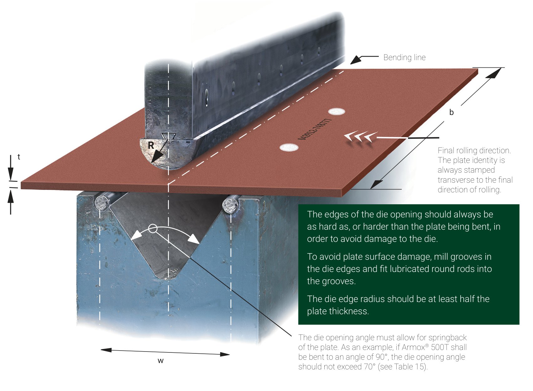
Picture 6. Minimum recommended punch radius (R) and die opening width (W) for plate thickness (t) when the plate is bent to 90° parallel to the final rolling direction and transverse to the final rolling direction — and also the corresponding springback.
Bending transverse to the final rolling direction
- Bending at right angles to the rolling direction
- Grind away any blemishes before bending
- Sheared edges should also be ground away
The identity of the plate is always stamped across the rolling direction. Avoid placing the plate so that the stamping occurs in the bend line, due to the risk of cracking. The edges of the die opening should always be as hard as or harder than the plate being bent, in order to avoid damage to the die.
A simple way of achieving this is to mill grooves in the die edges and fit lubricated rods of hardened tool steel into the grooves. The edge radius of the die should be at least half the plate thickness. The die opening angle must allow for springback of the plate without bottoming out in the tool. As an example, if Armox® 500T is to be bent to an angle of 90°, the die opening angle should not be greater than 70° (see Table 15).
The plate
Steel grade. Note that the bending force and springback increase with the plate strength. Harder plates give:
- increased bending force
- increased springback
- larger top tool radius
Plate surface. Our recommendations apply to shot blast and anti-corrosion painted plate. Surface damage and rust which is under tension during bending may greatly reduce the bendability. In critical cases, such defects can often be removed with careful grinding. Grinding scratches shall preferably be placed perpendicular to the bend line.
Plate edges. Cut and sheared edges should be deburred and rounded with a grinder.
Direction of rolling of the plate. The plate can be bent to a smaller radius at right angles to the direction of rolling than in the direction of rolling. See Picture 6 and Table 15.
Bend length (b). If the bend length is less than 10 times the plate thickness, the plate can often be bent to a smaller radius than the values given in Table 15.
The tools
Punch radius (R). The correct punch radius, along with the die width, is the most important parameter when bending Armox® (see Table 15). When bending high strength steel, the final inner radius often becomes somewhat smaller than the radius of the punch. When there is low friction between plate and tools, the phenomenon becomes more obvious.
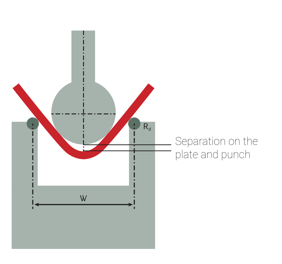
Picture 7. Separation of the plate during bending.
Table 15. The minimum recommended punch radius (R) and die opening width (W) for plate thickness (t) when the plate is being bent to 90° parallel or perpendicular to the final rolling direction.
Armox® grade | Thickness [mm] | Transverse R/t | Parallel R/t | Recommended W/t |
|---|---|---|---|---|
Armox® 370T Class 1 | < 8 | 3.0 | 3.5 | 10 |
Armox® 370T Class 1 | 8–14.9 | 4.0 | 4.0 | 10 |
Armox® 370T Class 1 | ≥ 15 | 5.0 | 5.5 | 10 |
Armox® 370T Class 2 | < 15 | 2.5 | 2.5 | 10 |
Armox® 370T Class 2 | ≥ 15 | 2.5 | 3.0 | 10 |
Armox® 440T | < 15 | 4.0 | 4.0 | 12 |
Armox® 440T | ≥ 15 | 4.5 | 4.5 | 14 |
Armox® 500T | < 15 | 4.0 | 4.0 | 14 |
Armox® 500T | ≥ 15 | 5.5 | 5.5 | 16 |
Armox® 520T | < 12 | 4.0 | 4.0 | 14 |
Armox® 560T | ≤ 15 | 4.5 | 4.5 | 14 |
Armox® 600T | < 15 | 5.0 | 5.0 | 15 |
Armox® 600T | ≥ 15 | 6.0 | 6.0 | 18 |
Armox® 620T | Contact SSAB | |||
Armox® Advance | Contact SSAB | |||
Care should be taken during all bending — due to the high strength of the plate and the high bending force necessary. If the plate should crack, fragments of the material may fly off. During bending, the operator and other personnel must therefore not stand in front of the equipment — they should move to the side.
Die opening width (W). Table 15 specifies the minimum recommended die opening. If the width is increased, the bending force and indentation marks will admittedly be reduced, but at the expense of increased springback.
Note that the opening angle must be small enough to allow a sufficient amount of over-bending (see Picture 7 and Table 15). In roll bending, the springback will be much larger.
Bending procedure
Friction. The die edges must be clean and undamaged. The bending force needed and the risk of cracking can be reduced by using round rods free to rotate as die edges and/or by lubricating the die edges.
Bending angle. The recommendations in Table 15 relate to bending to an angle of 90 degrees. Note that the bending angle has a lesser effect on the force needed and the springback than the die opening width and steel grade. Springback can be compensated by over-bending.
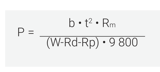
Bending force (P). To make an estimation of the force needed during bending, we pay attention not only to the bend length, plate thickness, die width and tensile strength, but also the changing moment arm during bending. The peak load is assumed to be reached at a bend opening angle of 120° with normal friction (no lubrication). Trial tests are always recommended.
- P = Bend force, tons (metric)
- t = Plate thickness, mm
- W = Die width, mm (Picture 6)
- b = Bend length, mm
- Rm = Tensile strength, MPa
- Rd = Die entry radius, mm
- Rp = Punch radius, mm
Die width
Springback increases with increased die width, while punch force is reduced. Make sure that the opening angle of the die allows for over-bending without bottoming out, to compensate for springback. An increased die opening width can in many cases lower the strain level in the bend. Also, make sure that there is enough room for the chosen punch together with the workpiece, in the die, during bending, without deforming the die. The minimum recommended die opening widths are shown in Table 15.
The die should preferably be equipped with round lubricated rods of hardened tool steel as mentioned earlier. If the die doesn’t have rollers, the die edge radius should be at least half of the plate thickness. Alternatively, the die width should be increased in order to minimize pressure on the die edge radius, and consequently reduce the risk of die marks. To avoid excessive tool wear, tooling should be harder than the workpiece.
Contact and more information
Contact your local SSAB representative or Tech Support at [email protected], or visit www.ssab.com.
This leaflet contains general suggestions and calculation models. It is the responsibility of the user to adapt the recommendations contained herein to the requirements of individual applications.