




Hardox® Welding
Welding of Hardox® wear plate
The Hardox® wear plate range, which also includes sheet, round bars, pipes and tubes, combines unique performance with exceptional weldability. Any conventional welding method can be used for welding Hardox® steel to other weldable steel.
This brochure contains useful tips and information for anyone who wants to simplify and boost the efficiency of their welding processes. It offers advice on preheating and interpass temperatures, heat input, welding consumables and more.
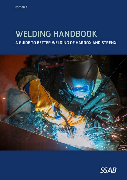
SSAB Welding Handbook
If you like to explore the world of welding even deeper, we recommend the SSAB Welding Handbook. This 132 page document provides a wealth of insights and recommendations for technicians, engineers and other professionals. It contains recommendations for achieving the best welding result when welding Hardox® wear plate and Strenx® performance steel. It describes the thermal flow and cycle, how to eliminate the risk of cracks, HAZ improvements, choice of consumables and filler material, and joint geometry characteristics.
You can download a digital version or order a printed version of the SSAB Welding Handbook at ssab.com/support/steel-handbooks.
References are also made to TechSupport documents, which address topics such as measures to avoid discontinuities and give examples of suitable consumables suppliers (Download Center at ssab.com/download-center), and to WeldCalc™, which as a desktop or app version allows users to optimize their welding performance based on the specific conditions and requirements of their welded structure (ssab.com/support/calculators-and-tools).
Methods for joint preparation
Joints can be prepared by conventional methods such as thermal cutting and machining. If thermal cutting is used, a thin oxide or nitride layer will be present that is approximately up to 0.2 mm (0.0079”) thick. These layers are removed before welding, usually by grinding.
Important parameters for welding
To ensure a high-quality weld, clean the weld area to remove moisture, oil, corrosion or any impurities prior to welding. In addition to good welding hygiene, make especially sure you consider the following aspects:
- Choice of welding consumables
- Preheating and interpass temperatures
- Heat input
- Weld sequence and size of root gap in the joint
Heat input
Excessive heat input increases the width of the heat affected zone (HAZ), which in turn impairs the mechanical properties as well as the wear resistance of the HAZ. Welding with low heat input provides benefits such as:
- Increased wear resistance of the HAZ
- Decreased distortion (single-pass welded joints)
- Increased toughness of the joint
- Increased strength of the joint
Most welding procedures are carried out with DC or AC welding. For DC and AC welding, the heat input is calculated according to the formulas below. The heat input for pulsed arc welding can be determined by either of the two alternative formulas.
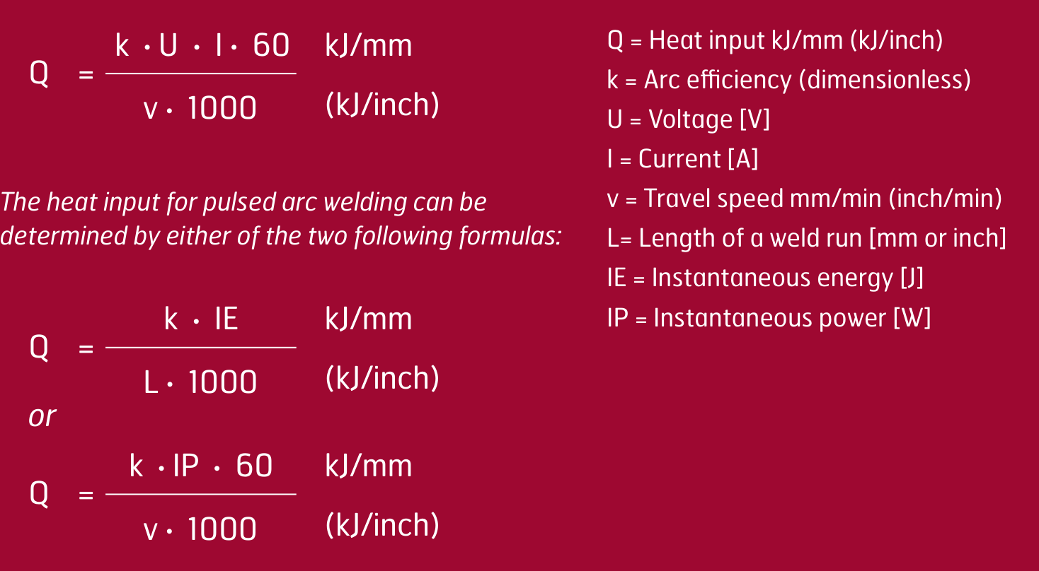
Heat input formulas. For DC and AC welding, and the two alternatives for pulsed arc welding, with the symbols used.
Table 1. Thermal efficiency factors of different welding methods.
Weld method | Thermal efficiency (k) |
|---|---|
MAG / GMAW | 0.8 |
MMA / SMAW | 0.8 |
SAW | 1.0 |
TIG / GTAW | 0.6 |
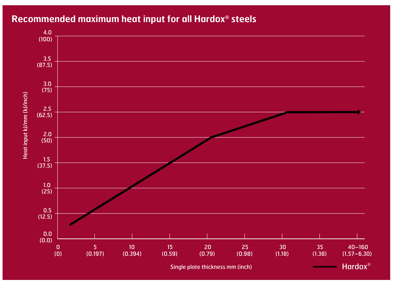
A very low heat input might, however, negatively affect the impact toughness (t8/5 values below 3 seconds — see the cooling time section). Table 2 indicates the recommended maximum heat input (Q) for Hardox®.
Table 2. Recommended maximum heat input for all Hardox® steels, against single plate thickness.
Avoiding hydrogen cracking
Due to a relatively low carbon equivalent, all Hardox® grades resist hydrogen cracking better than other wear-resistant steels. Minimize the risk of hydrogen cracking by following these recommendations:
- Preheat the weld area to the recommended minimum temperature.
- Measure the preheat temperature according to the preheating recommendations.
- Use processes and consumables that provide a maximum hydrogen content of 5 ml/100 g weld metal.
- Keep the joint clear from impurities like rust, grease, oil or frost.
- Use only classifications for welding consumables recommended by SSAB.
- Apply a proper welding sequence in order to minimize residual stresses.
- Place weld starts and stops preferably at least 50-100 mm (2”-4”) from a corner in order to avoid excessive stresses in these regions; see Figure 1.
- Avoid a root opening size exceeding 3 mm (1/8”); see Figure 2.
- Gap size should not exceed 3 mm (1/8”); see Figure 2.
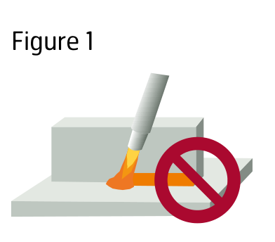
Figure 1. Avoid placing weld starts and stops in a corner.
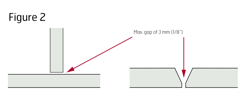
Figure 2. Maximum gap of 3 mm (1/8”).
Minimum preheating and interpass temperatures
It is essential to follow the recommended minimum preheating temperature as well as the procedure for obtaining and measuring the temperature in and around the joint in order to avoid hydrogen cracking.
Influence of alloying elements on the selection of preheating and interpass temperatures
A unique combination of alloying elements optimizes the mechanical properties of Hardox® wear plate. This combination governs preheating and interpass temperatures of Hardox® steel during welding, and can be used to calculate the carbon equivalent. The carbon equivalent is usually expressed as CEV or CET.
The alloying elements are specified in the mill certificate of Hardox® steel and are stated in weight percentages in the two formulas. A higher carbon equivalent usually requires a higher preheating and interpass temperature. The typical carbon equivalent for all Hardox® grades is guaranteed in SSAB's product data sheets which can be found at www.hardox.com.
However, if the minimum preheat temperatures stated in this brochure are followed, calculation of the carbon equivalent is not needed.
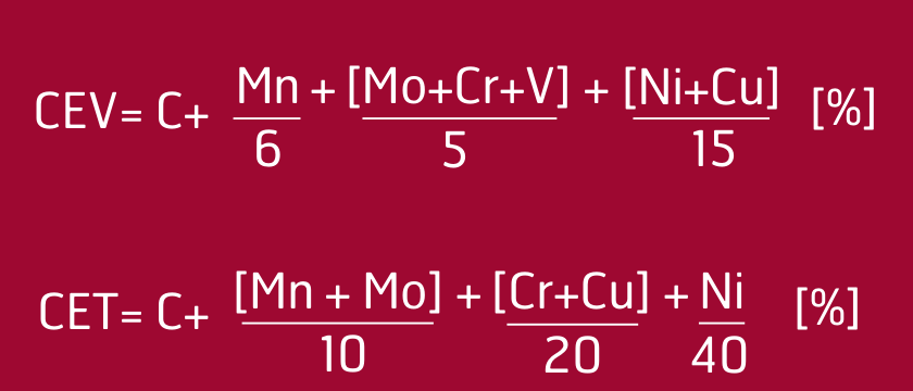
Carbon equivalents. The CET and CEV formulas.
Preheating and interpass temperatures for the entire Hardox® range
Minimum recommended preheat and maximum interpass temperatures during welding are shown in Tables 3, 4a and 4b. Unless otherwise stated, these values are applicable for welding with unalloyed and low-alloyed welding consumables.
- When plates of different thicknesses but of the same steel grade are welded together, the thicker plate determines the required preheating and interpass temperatures; see Figure 4.
- When different steel types are welded together, the plate requiring the highest preheating temperature determines the required preheat and interpass temperatures.
- Tables 4a and 4b are applicable for heat inputs of 1.7 kJ/mm (43.2 kJ/inch) or higher. If heat inputs of 1.0–1.69 kJ/mm (25.4–42.9 kJ/inch) are used, we recommend that you increase the temperature by 25 °C (77 °F) above the recommended preheating temperature.
- If a lower heat input than 1.0 kJ/mm (25.4 kJ/inch) is applied, we recommend that you use SSAB’s WeldCalc app to calculate the recommended minimum preheating temperature.
- If the ambient humidity is high or the temperature is below 5 °C (41 °F), the lowest recommended preheating temperatures given in Tables 4a and 4b should be increased by 25 °C (77 °F).
- For plates thicker than 25 mm (0.984”), and joint geometries where the root pass is close to the centerline of the plate such as double-V butt welds, we recommend to shift the root pass approximately 5 mm (0.197”) away from the centerline of the plate.
The interpass temperature shown in Table 3 is the maximum recommended temperature in the joint (on top of the weld metal) or immediately adjacent to the joint (start position), just before starting the next weld pass.
The minimum recommended preheating and maximum interpass temperatures shown in Tables 3, 4a and 4b are not affected at heat inputs higher than 1.7 kJ/mm (43.2 kJ/inch). The information is based on the assumption that the welded joint is allowed to air cool to ambient temperature.
Note that these recommendations also apply to tack welds and root runs. In general, each of the tack welds should be at least 50 mm (2”) long. For joints with plate thicknesses of up to 8 mm (0.31”), shorter tack lengths may be used. The distance between tack welds can be varied as required.
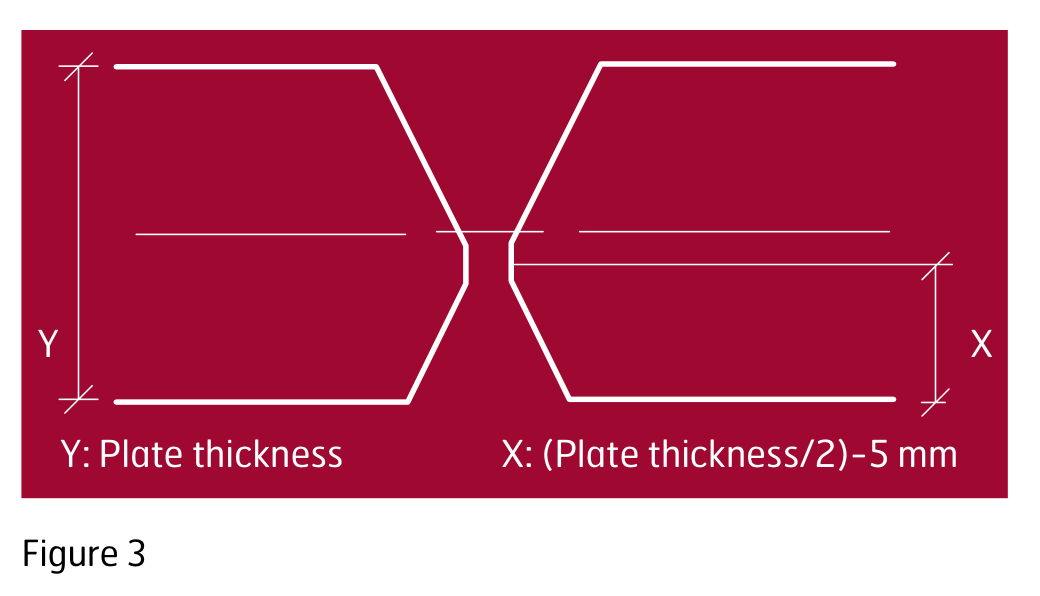
Figure 3. For plates thicker than 25 mm, shift the root pass about 5 mm away from the centerline. Y is the plate thickness, X is (plate thickness / 2) − 5 mm.
Table 3. Maximum recommended interpass and preheating temperatures.
Grade | Maximum recommended interpass temperature / preheating temperature |
|---|---|
Hardox® HiTemp** | 300 °C (572 °F) |
Hardox® HiTuf** | 300 °C (572 °F) |
Hardox® HiAce | 225 °C (437 °F) |
Hardox® 400 / 400 Tube and Round bar | 225 °C (437 °F) |
Hardox® 450 | 225 °C (437 °F) |
Hardox® 500 / 500 Tube | 225 °C (437 °F) |
Hardox® 500 Tuf | 225 °C (437 °F) |
Hardox® 550 | 225 °C (437 °F) |
Hardox® 600 | 225 °C (437 °F) |
Hardox® Extreme | 100 °C (212 °F) |
**Interpass temperatures of up to approx. 400 °C (752 °F) can be used in certain cases for Hardox® HiTemp and Hardox® HiTuf. In such cases, use WeldCalc™.
Recommended preheating temperatures
The single plate thickness (diameter) is shown on the x-axis of the charts below. Minimum recommended preheat and interpass temperatures are given for different single plate thicknesses. Note that every increase in temperature starts at 0.1 mm (0.004”) above the indicated thickness in the charts.
- The preheating temperature for Hardox® 400 also applies to Hardox® 400 Tubes, which are available in thicknesses of 3–6 mm (0.118”–0.236”).
- The preheating temperature for Hardox® 500 also applies to Hardox® 500 Tubes, which are available in thicknesses of 3–6 mm (0.118”–0.236”).
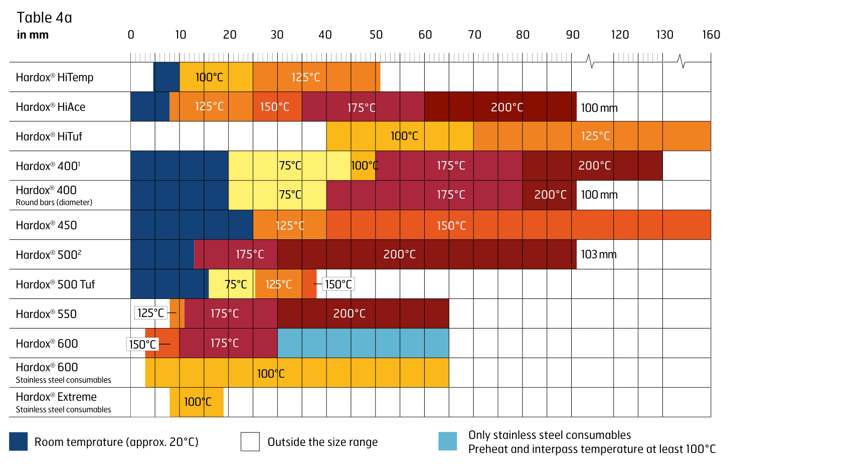
Table 4a. Minimum recommended preheat and interpass temperature by single plate thickness, in mm. Dark blue is room temperature (approx. 20 °C), light blue is stainless steel consumables only with preheat and interpass temperature at least 100 °C, and white is outside the size range.
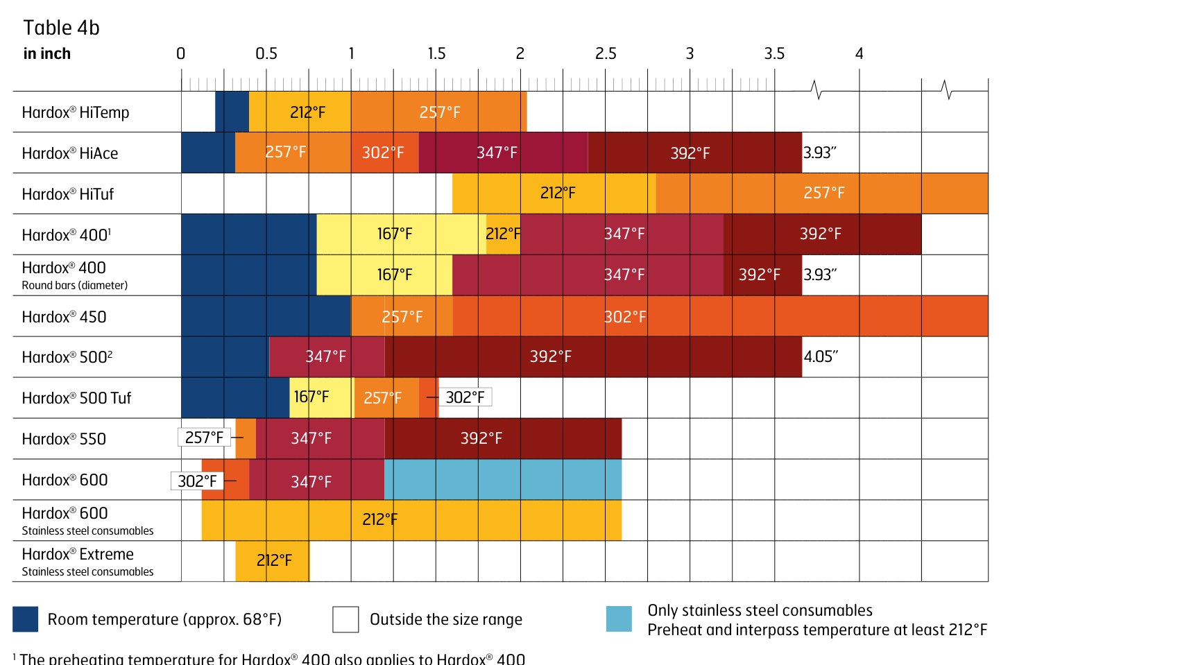
Table 4b. The same recommendation in inches, with room temperature at approx. 68 °F and the stainless-only band at least 212 °F.
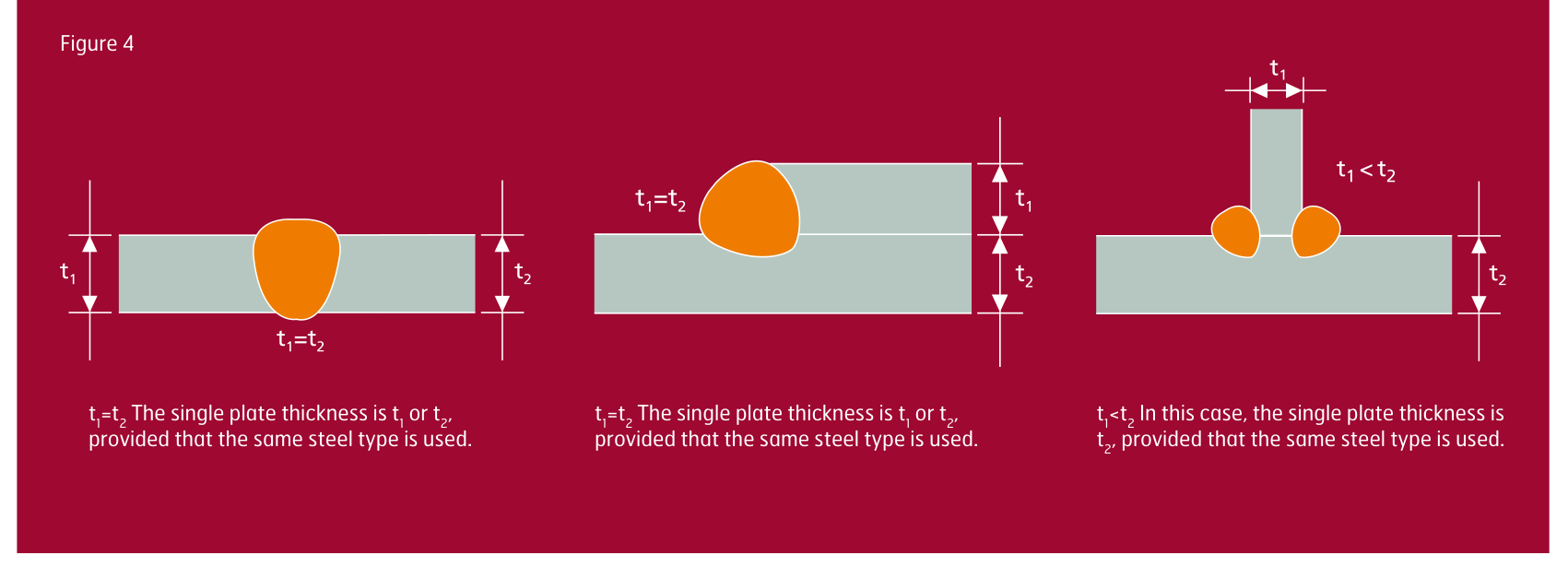
Figure 4. Schematic drawing showing single plate thickness (diameter). Where t1 = t2 the single plate thickness is either; where t1 < t2 it is t2, provided the same steel type is used.
Attaining and measuring the preheating temperature
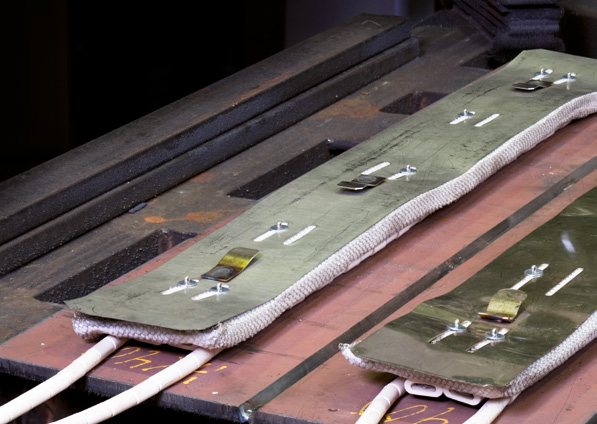
The required preheating temperature can be achieved in several ways. Electric preheater elements around the prepared joint are often best, since uniform heating of the area can be obtained. The temperature should be monitored by using, for example, a contact thermometer.
Figure 5. Example of electrical heating mats.
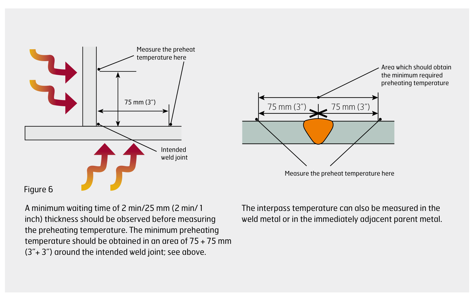
Figure 6. Recommended preheating operation. A minimum waiting time of 2 min/25 mm (2 min/1 inch) thickness should be observed before measuring the preheating temperature. The minimum preheating temperature should be obtained in an area of 75 + 75 mm (3” + 3”) around the intended weld joint. The interpass temperature can also be measured in the weld metal or in the immediately adjacent parent metal.
Hardfacing
If the weld joint is located in an area where high wear is expected, you can employ hardfacing with special consumables to increase the wear resistance of the weld metal. The instructions for both joining and hardfacing Hardox® steel should be followed.
Some consumables for hardfacing require a very high preheat temperature that may exceed the maximum recommended interpass temperature for Hardox® steel. It is worth noting that using a preheat temperature above the maximum recommended interpass temperature for Hardox® steel may reduce the hardness of the base plate and result in deterioration of wear resistance of the preheated area.
Minimum and maximum preheat temperatures are the same as for conventional types of welding; see Tables 4a and 4b.
It is beneficial to weld a buffer layer with extra-high toughness between the ordinary welded joint or plate and the hardfacing. The choice of consumables for the buffer layer should follow the welding recommendations for Hardox® wear plate. Stainless steel consumables in accordance with AWS 307 and AWS 309 should preferably be used for the buffer layer.
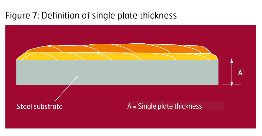
Figure 7. Definition of single plate thickness for hardfacing situations. A = single plate thickness.
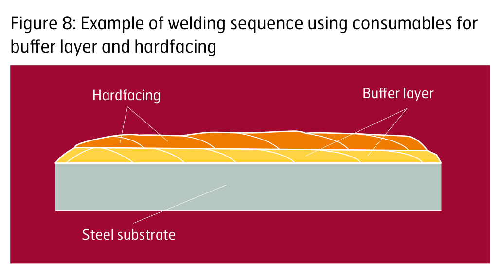
Figure 8. Example of welding sequence using consumables for buffer layer and hardfacing.
Recommendations for minimizing distortion
The amount of distortion during and after welding is related to the base plate thickness and welding procedure. Minimize distortion, particularly when welding thinner gauges, by following these recommendations:
- Weld with a heat input as low as possible (single pass welded joints).
- Minimize the cross sectional area; see Figure 9.
- Use symmetrical welds; see Figure 10.
- Preset, clamp or angle the parts before welding in order to compensate for the deformation; see Figure 11.
- Avoid an irregular root opening.
- Minimize reinforcements and optimize the throat thickness of the fillet welds.
- Decrease spacing between the tack welds.
- Use a back-step welding technique or a step welding technique. In back-step welding, all weld passes are welded in the opposite direction to the general progression. In skip welding, all weld sequences do not need to be directed opposite to the general progression; see Figure 12.
- Weld from rigid areas to loose ends; see Figure 13.
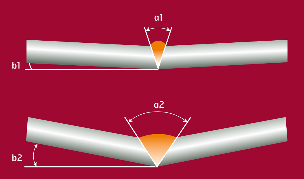
Figure 9. Cross section of the weld and how it influences the angle deviation.
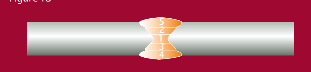
Figure 10. A symmetrical weld.
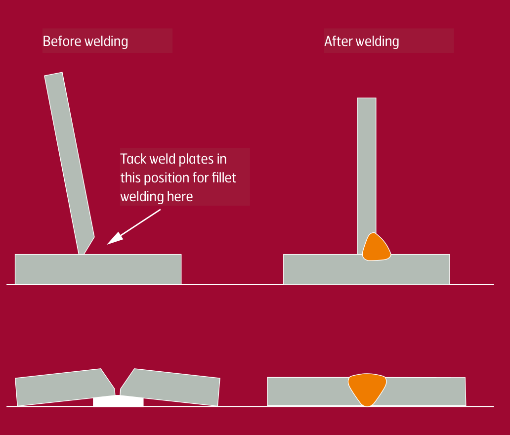
Figure 11. Presetting of a fillet joint and a single-V butt joint, before and after welding.
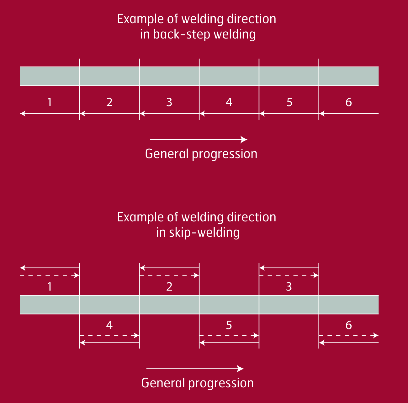
Figure 12. Use a symmetrical weld sequence — back-step welding above, skip welding below, both against the general progression.
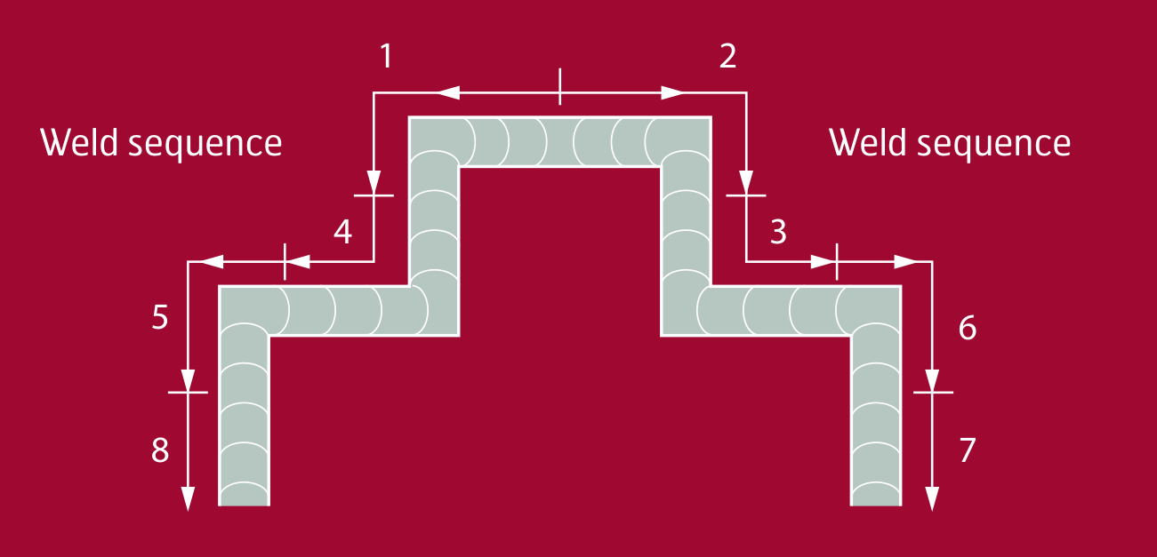
Figure 13. Weld sequence from rigid areas to loose ends.

Cooling time t8/5
The cooling time (t8/5) is the time that it takes for the weld to cool from 800 °C to 500 °C (1,472 °F to 932 °F), and it gives a good description of the thermal effect from welding.
Recommended cooling times are often provided for structural steels in order to optimize the weld process for a certain requirement, such as meeting the minimum impact toughness. Recommended maximum cooling times for different Hardox® grades are available in SSAB’s WeldCalc app.

WeldCalc™
The SSAB WeldCalc app provides you with the right welding machine settings, including recommended heat input, preheating temperatures, amps, volts and travel speed. Download the WeldCalc app or the desktop version at ssab.com/support/calculators-and-tools.
Welding sequence and root opening size
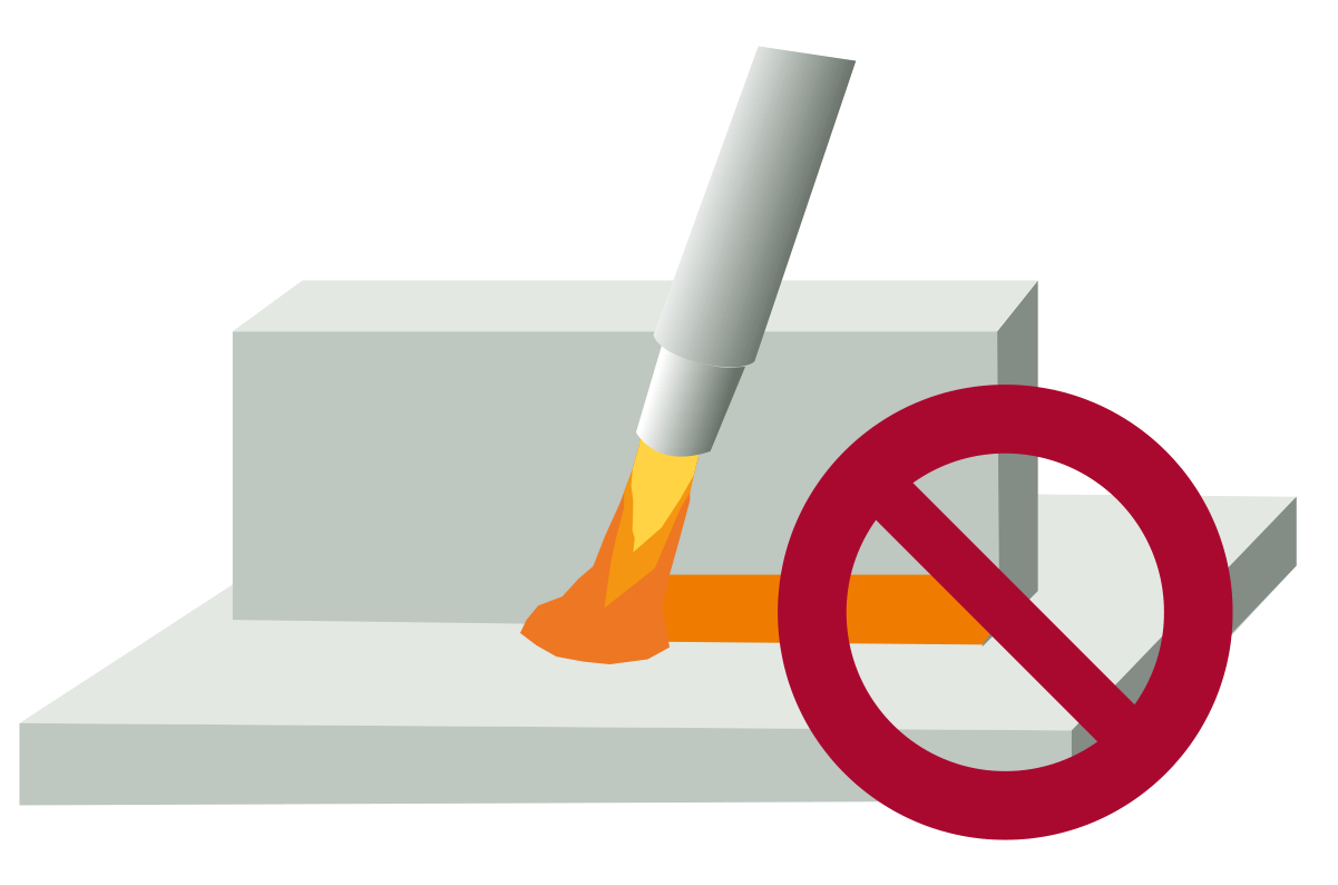
Before tack welding, it is important to maintain a root opening between base plates not exceeding 3 mm (1/8”). Aim for as uniform a gap size along the joint as possible. Also, avoid weld starts and weld stops in highly stressed areas. If possible, the start and stop procedures should be at least 50-100 mm (2”-4”) from a corner. When welding to the edge of plates, a runoff weld tab would be beneficial.
Figure 14. Avoid starts and stops in highly stressed areas like corners. Gap size should not exceed 3 mm (1/8”).
Welding consumables
Strength of unalloyed and low-alloyed welding consumables
Unalloyed and low-alloyed consumables with a maximum yield strength of 500 MPa (72 ksi) are generally recommended for Hardox® steel. Consumables of higher strength (Re max. 900 MPa / 130 ksi) may be used for Hardox® 400 and 450 in the thickness range of 0.7-6.0 mm (0.028”-0.236”).
Low-alloyed consumables result in higher hardness of the weld metal which can reduce the wear rate of the weld metal. If the wear properties of the weld metal are essential, the top cap of the joint could be welded with consumables used for hardfacing.
Requirements on hydrogen content
The hydrogen content should be lower than or equal to 5 ml of hydrogen per 100 g of weld metal when welding with unalloyed or low-alloyed welding consumables.
Solid wire used in MAG/GMA and TIG/GTA welding can produce these low hydrogen contents in weld metal. Hydrogen content for other types of welding consumables should be obtained from the respective manufacturers. SSAB provides examples of suitable consumables in TechSupport No. 60, available at ssab.com.
If consumables are stored in accordance with the manufacturer’s recommendations, the hydrogen content will be maintained to meet the requirement. This also applies to all coated consumables and fluxes.
Table 5. Recommended consumables for all steels in the Hardox® wear plate product range.
Welding method | AWS classification | EN classification |
|---|---|---|
MAG / GMAW, solid wire | AWS A5.28 ER70X-X AWS A5.28 ER80X-X | EN ISO 14341-A- G 42x EN ISO 14341-A- G 46x |
MAG / MCAW, metal cored wire | AWS A5.28 E7XC-X AWS A5.28 E8XC-X | EN ISO 17632-A- T 42xH5 EN ISO 17632-A- T 46xH5 |
MAG / FCAW, flux cored wire | AWS A5.29 E7XT-X AWS A5.29 E8XT-X | EN ISO 17632-A- T 42xH5 EN ISO 17632-A- T 46xH5 |
MMA (SMAW, stick) | AWS A5.5 E70X AWS A5.5 E80X | EN ISO 2560-A- E 42xH5 EN ISO 2560-A- E 46xH5 |
SAW | AWS A5.23 F49X AWS A5.23 F55X | EN ISO 14171-A- S 42x EN ISO 14171-A- S 46x |
TIG / GTAW | AWS A5.18 ER70X AWS A5.28 ER80X | EN ISO 636-A- W 42x EN ISO 636-A- W 46x |
X stands for one or more characters.
Stainless steel welding consumables
Consumables of austenitic stainless steels can be used for welding all Hardox® products, as shown in Table 6. They allow welding at room temperature between 5-20 °C (41-68 °F) without preheating, except for Hardox® 600 and Hardox® Extreme.
SSAB recommends giving first preference to consumables in accordance with AWS 307 and second preference to those in accordance with AWS 309. These types of consumables have a yield strength of up to approximately 500 MPa (72 ksi) in all weld metal.
The AWS 307 type can withstand hot cracking better than AWS 309. It should be noted that manufacturers seldom specify the hydrogen content of stainless steel consumables, since hydrogen does not affect the performance as much as it does in unalloyed and low-alloyed consumables. SSAB does not impose any restrictions on the maximum hydrogen content for these types of consumables. Examples of suitable stainless consumables can be found in TechSupport No. 60, available at ssab.com.
Table 6. Recommended stainless steel consumables for the Hardox® wear plate product range.
Welding method | AWS classification | EN classification |
|---|---|---|
MAG / GMAW, solid wire | Recommended: AWS A5.9: ER307 Suitable: AWS A5.9: ER309 | Recommended: EN ISO 14343-A: B 18 8 Mn / EN ISO 14343-B: SS307 Suitable: EN ISO 14343-A: B 23 12 X / EN ISO 14343-B: SS309X |
MAG / MCAW, metal cored wire | Recommended: AWS A5.9: EC307 Suitable: AWS A5.9: EC309 | Recommended: EN ISO 17633-A: T 18 8 Mn / EN ISO 17633-B: TS307 Suitable: EN ISO 17633-A: T 23 12 X / EN ISO 17633-B: TS309X |
MAG / FCAW, flux cored wire | Recommended: AWS A5.22: E307T-X Suitable: AWS A5.22: E309T-X | Recommended: EN ISO 17633-A: T 18 8 Mn / EN ISO 17633-B: TS307 Suitable: EN ISO 17633-A: T 23 12 X / EN ISO 17633-B: TS309X |
MMA / SMAW, stick | Recommended: AWS A5.4: E307-X Suitable: AWS A5.4: E309-X | Recommended: EN ISO 3581-A: 18 18 Mn / EN ISO 3581-B: 307 Suitable: EN ISO 3581-A: 22 12 X / EN ISO 3581-B: 309X |
SAW | Recommended: AWS A5.9: ER307 Suitable: AWS A5.9: ER309 | Recommended: EN ISO 14343-A: B 18 8 Mn / EN ISO 14343-B: SS307 Suitable: EN ISO 14343-A: S 23 12 X / EN ISO 14343-B: SS309X |
TIG / GTAW | Recommended: AWS A5.9: ER307 Suitable: AWS A5.9: ER309 | Recommended: EN ISO 14343-A: W 18 8 Mn / EN ISO 14343-B: SS307 Suitable: EN ISO 14343-A: W 23 12 X / EN ISO 14343-B: SS309X |
X stands for one or more characters. The EN prefixes are transcribed exactly as printed; see the note in the bundle README about B where G or S is expected.
Shielding gas
Shielding gases for Hardox® wear plate are generally the same as usually selected for unalloyed and low-alloyed steels. Shielding gases used for MAG/GMA welding of Hardox® steels usually contain a mixture of argon (Ar) and carbon dioxide (CO₂). A small amount of oxygen (O₂) is sometimes used together with Ar and CO₂ in order to stabilize the arc and reduce the amount of spatter.
A shielding gas mixture of about 18–20% CO₂ in argon is recommended for manual welding, which facilitates good penetration in the material with a reasonable amount of spatter. If automatic or robot welding is used, a shielding gas containing 8–10% CO₂ in argon could be used in order to optimize the weld result with regards to the productivity and spatter level.
In all welding methods based on shielding gas, the flow of shielding gas depends on the welding situation. As a general guideline, the shielding gas flow in l/min should be set to the same value as the inside diameter of the gas nozzle measured in mm.
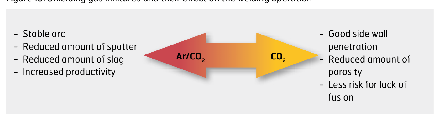
Figure 15. Shielding gas mixtures and their effect on the welding operation, from an argon/CO₂ mixture towards pure CO₂.
Table 7. Examples of shielding gas mixtures and recommendations. The mixtures given can be used for both short-arc and spray-arc welding.
Welding method | Arc type | Position | Shielding gas |
|---|---|---|---|
MAG / GMAW, solid wire | Short arc | All positions | 18 – 25% CO₂ in Ar |
MAG / MCAW, metal cored wire | Short arc | All positions | 18 – 25% CO₂ in Ar |
MAG / GMAW, solid wire | Spray arc | Flat position | 15 – 20% CO₂ in Ar |
MAG / FCAW, flux cored wire | Spray arc | All positions | 15 – 20% CO₂ in Ar |
MAG / MCAW, metal cored wire and FCAW basic flux cored wire | Spray arc | Flat position | 15 – 20% CO₂ in Ar |
Robotic and automated MAG / GMAW | Spray arc | Flat position | 8 – 18% CO₂ in Ar |
TIG / GTAW | All positions | 100% Ar |
Welding on primer
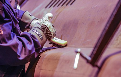
You can weld directly on the primer used on Hardox® wear plate thanks to its low zinc content. The primer can be easily brushed or ground away in the area around the joint.
Removing primer prior to welding can be beneficial, since it can minimize the porosity in the weld and can facilitate out-of-position welding. If primer remains on the weld surface, then the sub-surface and surface porosity of the weld may be slightly higher. FCAW with basic flux offers the lowest porosity.
It is important to maintain good normal ventilated manufacturing premises to avoid the harmful effect the primer could have on the welder and surroundings.
The primer is easy to brush away if necessary.
Post-weld heat treatment
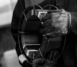
Hardox® HiTuf and Hardox® HiTemp can be stress relieved by post-weld heat treatment, although this is rarely necessary. Other Hardox® steels should not use this method for stress relieving, since this may impair the mechanical properties. For more information, consult the Welding Handbook from SSAB, available at ssab.com/support/steel-handbooks.
The latest in welding technology
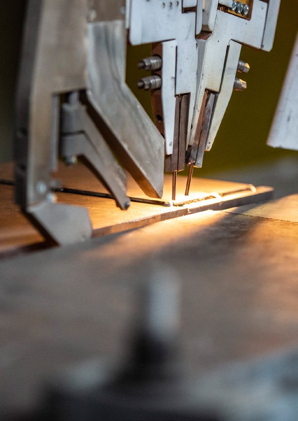
At SSAB’s own welding stations at our R&D Centers, we continuously test cutting-edge technologies and machines to bring you the best welding recommendations.
With SAW narrow-gap technology using one or two wires, you can weld thicker plate thicknesses of the Hardox® wear plate. You get high-quality results with less welding wire and flux powder while reducing machine runtime, saving energy and lowering production costs. And with SAW ICE (integrated cold electrode), you can use a higher welding speed, a lower heat input and get a higher deposition rate than with conventional methods.
Whichever process is right for you, we’ll help make sure you achieve better welded material properties and higher productivity rates.
Contact and more information
Contact your local SSAB representative or Tech Support at [email protected], or visit hardox.com.
Hardox® is a trademark of the SSAB group of companies. The information contained in this brochure is provided only as general information. It is the user’s responsibility to independently determine suitability of all products and applications, and to test and verify the same.