




Hardox® Cutting
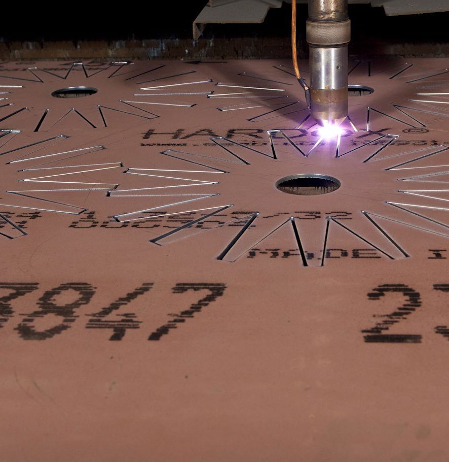
Cutting Hardox® wear plate
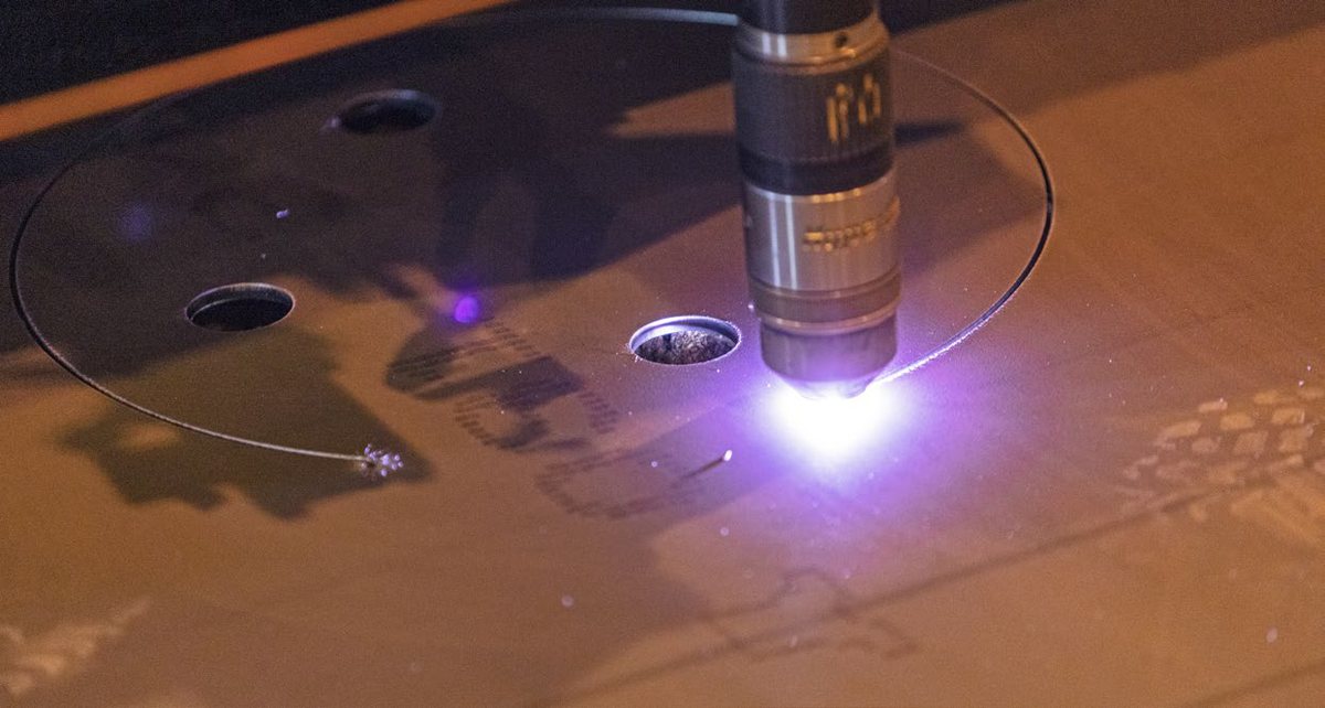
Hardox® grades are suitable for all thermal cutting methods, including oxy-fuel cutting, plasma cutting and laser cutting. Of course, you can also use many common cold cutting processes like abrasive water jet (AWJ) cutting and sawing.
The enhanced thermal cutting performance of the Hardox® grades is primarily derived from their low alloy content together with their very low levels of impurities. Other favorable properties that can be utilized for laser cutting include the steel’s narrow thickness tolerances and smooth plate surfaces. Many of the Hardox® grades can, at moderate thicknesses, be thermally cut using the same parameters as for mild steels.
In some cases, you need to adapt the parameters to minimize the risk for hydrogen cracking. Other issues to be aware of that relate to the steel’s characteristics are:
- The change in mechanical properties in the thermally affected part of the steel — the heat-affected zone (HAZ) — due to cutting.
- The distortions caused by thermal cutting. Due to the higher levels of stresses, Hardox® plates are prone to more movement during thermal cutting than ordinary steels.
The gases for the different thermal cutting methods are selected and applied in the same way as for unalloyed and low-alloyed steels with yield strengths up to 355 MPa. There are different gas compositions and application parameters that are suitable for the thermal cutting methods. SSAB does not have any further stated recommendations in this respect for the Hardox® grades.
The cold cutting methods, shearing and punching, are limited to Hardox® 400 and Hardox® 450 up to 10 mm (0.394”) in plate thickness. AWJ cutting is a cold cutting method that provides advantageous mechanical properties since it doesn’t result in an HAZ.
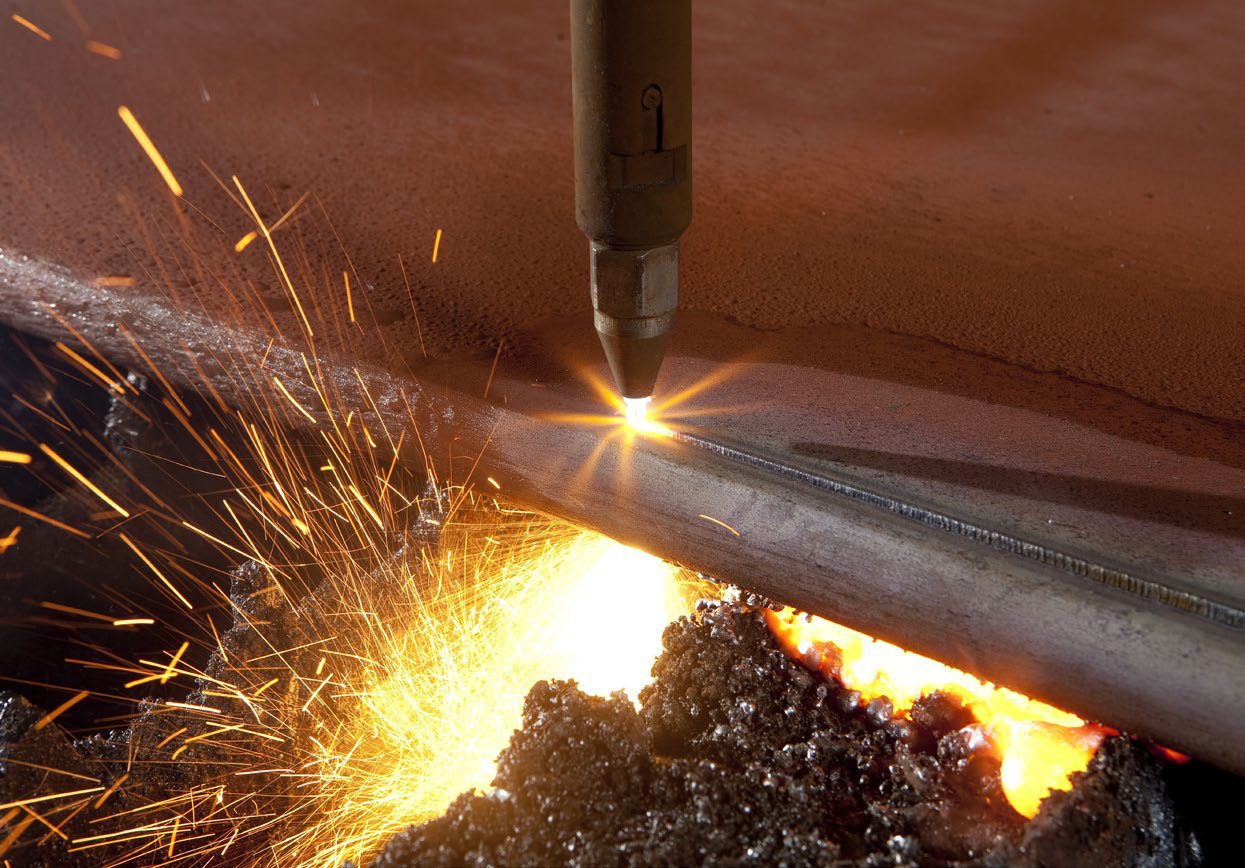
Cutting methods
Oxy-fuel cutting
Hardox® wear steel is easily cut using the oxy-fuel cutting process. Oxy-fuel cutting has almost no limitations when it comes to material thickness, so material thicknesses up to 1000 mm (39.370”) can be cut. The recommended minimum thickness for cutting is 10 mm (0.394”). Cutting thinner material should be performed with low heat methods such as plasma or laser cutting to minimize the risk for deformation and loss of hardness.
A common misunderstanding is that you need higher cutting oxygen pressure to cut hard steels. Oxy-fuel cutting is a thermal process whose performance remains unaffected by the hardness of the steel. Hardox® wear plate has a low alloying concept, which together with the cleanliness of the steel makes it easy to cut.
Table 1. General features for oxy-fuel cutting.
Cutting method | Kerf width | Heat-affected zone (HAZ) | Dimensional tolerances |
|---|---|---|---|
Oxy-fuel cutting | 2-5 mm (0.079-0.197”) | 4-10 mm (0.157-0.394”) | ± 2.0 mm (0.079”) |

Plasma cutting
Hardox® steel is easily cut using the plasma cutting process. Plasma cutting has a limitation when it comes to material thickness. The main thickness to be cut must be below 50 mm (1.969”) (depending on the plasma cutting machine).
There is no difference in plasma cutting Hardox® wear steel compared to ordinary mild steel. There is a reduced need for preheating or postheating when plasma cutting compared with oxy-fuel cutting. However, when plasma cutting thick Hardox® plate with oxygen as plasma gas, either preheating or postheating may be required. Use the same parameters as for oxy-fuel cutting (Table 6) to avoid cut edge cracking.
Table 2. General features for plasma cutting.
Cutting method | Kerf width | Heat-affected zone (HAZ) | Dimensional tolerances |
|---|---|---|---|
Plasma cutting | 2-6.5 mm (0.079-0.256”) | 2-5 mm (0.079-0.197”) | ± 1.0 mm (0.039”) |
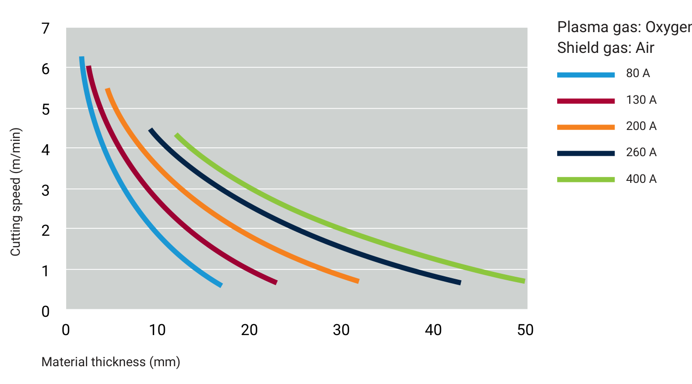
Figure 1. General cutting speeds for different plasma power sources, from 80 A to 400 A, with oxygen as plasma gas and air as shield gas.
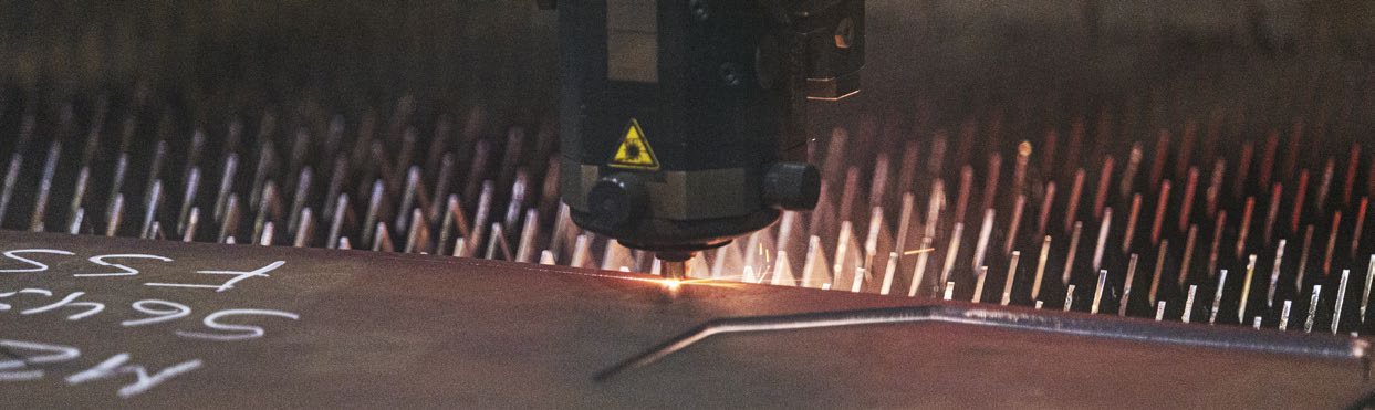
Laser cutting
Laser cutting of Hardox® material can easily be done by using the normal processing parameters for the given material thickness. The maximum thickness must be approximately 30 mm (1.181”) depending on the laser cutting equipment. Most commonly cut thicknesses are those below 25 mm (0.984”).
One of the benefits of laser cutting is the high cutting speed. Due to the relatively thin thicknesses and small thermal impact, preheating or postheating is not required during laser cutting of Hardox® steels. Preheating is instead detrimental to the cut edge quality.
There is no difference in laser cutting Hardox® steel compared with ordinary mild steel, so you can use the same process parameters. The primer reduces the cutting speed, but this can be solved by first vaporizing the primer and then cutting the contour with full speed.
Table 3. General features for laser cutting.
Cutting method | Kerf width | Heat-affected zone (HAZ) | Dimensional tolerances |
|---|---|---|---|
Laser cutting | < 1 mm (0.039”) | 0.2-2 mm (0.008-0.079”) | ± 0.2 mm (0.008”) |
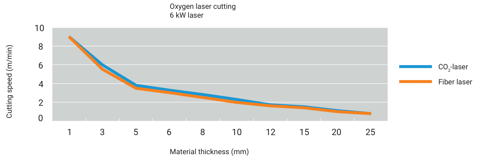
Figure 2a. Laser cutting speeds — oxygen laser cutting with a 6 kW laser, CO₂ laser against fiber laser.
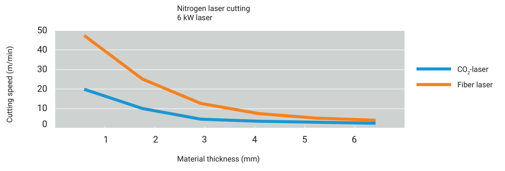
Figure 2b. Laser cutting speeds — nitrogen laser cutting with a 6 kW laser, CO₂ laser against fiber laser.
Hardness properties in the heat-affected zone (HAZ)
The properties of the HAZ depend on:
- Whether or not the steel was tempered during manufacturing and, if so, how it was carried out
- The chemical composition of the steel
- The impact of the thermal treatment from the cutting process
The width of the HAZ increases with increasing thermal impact from the cutting process. For instance, cutting with the same power and reducing the cutting speed leads to a wider HAZ. Different thermal cutting processes have different thermal impact, resulting in wider or narrower HAZ. Oxy-fuel cutting has the highest thermal impact followed by plasma cutting and laser cutting.
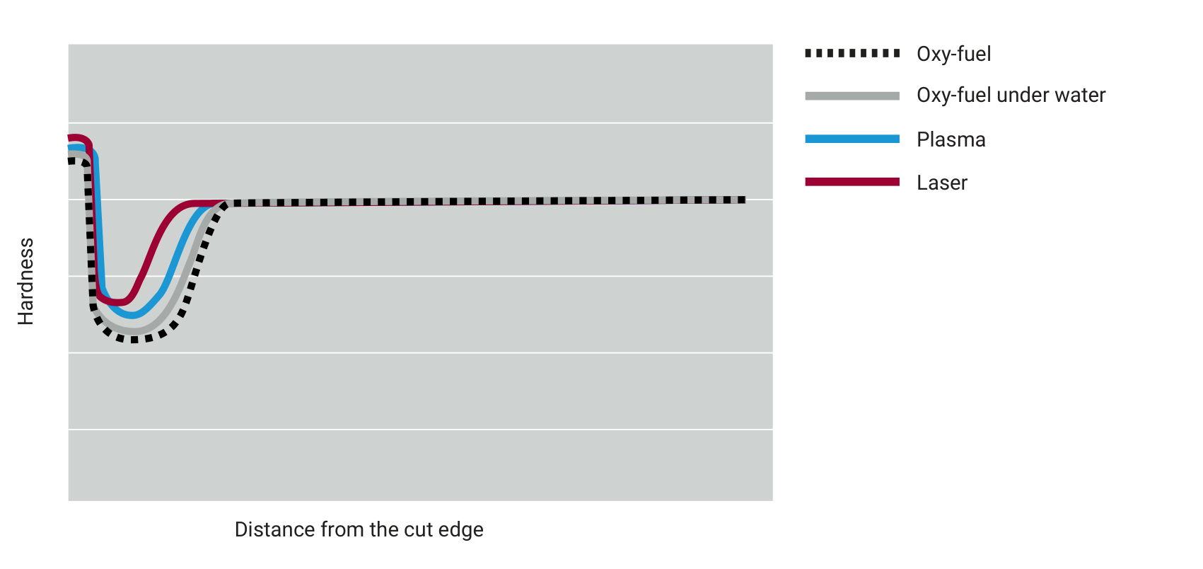
Figure 3. Schematic hardness profiles in the HAZ after thermal cutting of Hardox® wear steel with different cutting methods.
Cutting risks
Hydrogen cracks
Cut edge cracking is a phenomenon that is closely related to hydrogen cracking in welds, and most commonly occurs when thermal cutting methods are used. If cut edge cracks occur, they will become visible between 48 hours and up to several weeks after the cutting. The risk of cut edge cracking increases with the steel hardness and plate thickness, as is shown in Table 4. Even if cut edge cracking is usually related to thermal cutting, it can arise from sawing or abrasive water jet cutting in very hard materials.
In the first phase of crack formation, small cracks form in the center of the plate that run horizontally within the HAZ. They form just behind the cut edge and typically appear within a couple of hours after cutting. The cracks are not visible to the naked eye at this stage.
In the second phase, which typically occurs after a couple of days, the cracks propagate to the cut edge surface and build longer horizontal cracks, typically up to 5-10 cm (1.969-3.937”).
A third phase may take place, which normally occurs after a couple of weeks, where the crack propagation continues, changes direction and spreads up to the plate surface. Although vertical cracks are unusual, the risk for this increases with increasing hardness and thickness of the steel.
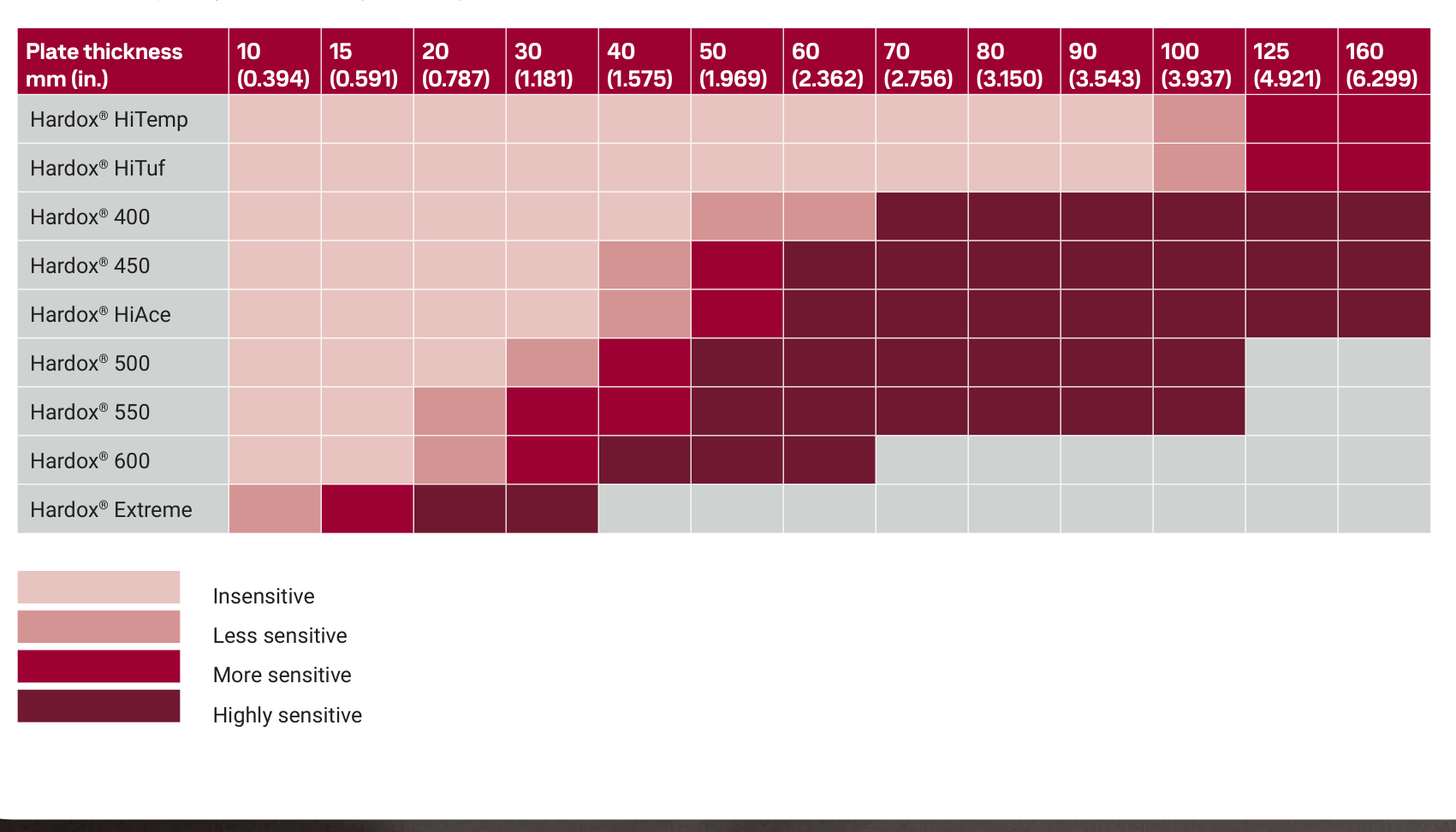
Table 4. Susceptibility to thermal edge cracking. Sensitivity is shown by cell colour across grade and plate thickness; grey means the grade is not supplied in that thickness.
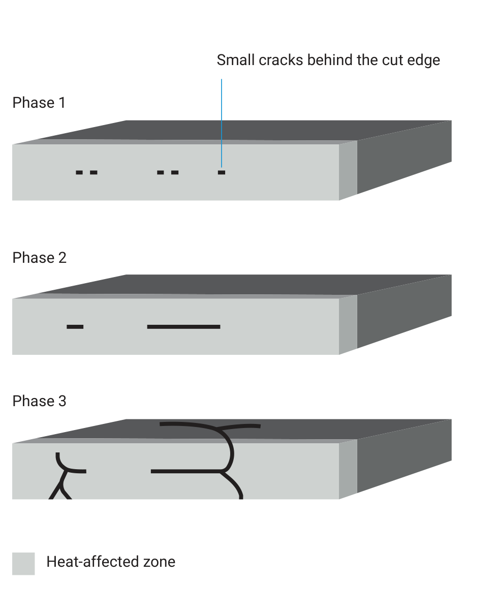
Figure 4. Formation of hydrogen cracks at, and around, the cut edge.
If a plate is cut into components, the as-delivered residual stresses will be relaxed. The smaller the component, the fewer the as-delivered residual stresses will remain. A small enough component will only contain residual stresses from the thermal cutting process. In addition, a small component has a shorter cut length than a big component. Hence chance also favors small components. A small enough cut component is not likely to crack.
Beveled edges are more susceptible to edge cracking than square edges. Due to its probabilistic nature, cracking in thermal cut edges cannot be predicted with accuracy. But we can strongly influence the odds for cracking through our choice of cutting procedure.
Three conditions must be present in the steel at the same time in order for hydrogen cracks to form. They are:
- A relatively high content of alloy elements.
- A high level of tensile stresses.
- A relatively high content of hydrogen in the material.
These factors interact with each other. Keeping their levels suitably low minimizes the risk of hydrogen cracks.
Table 5. Influence of component size on the probability of cut edge cracking in that piece.
Component size | 200x200 mm (7.874x7.874”) | 400x400 mm (15.748x15.748”) | 800x800 mm (31.496x31.496”) | 1600x1600 mm (62.992x62.992”) | Larger |
|---|---|---|---|---|---|
Relative edge cracking risk for one component | 1 | 10 | 100 | 1000 | 5000 |
The influence from alloying elements in the steel
The influence of alloying elements is the same for thermal cutting as for welding. This means that higher carbon equivalent values in the steel correspond to increased sensitivity to hydrogen cracks. In general terms, the carbon equivalent increases with increased thickness, hardness and strength of the Hardox® grade. Consequently there are more restrictions regarding the cutting of Hardox® grades with increasing hardness values, and greater plate thicknesses for a given Hardox® grade have more restrictions for minimizing the risk of hydrogen cracks during cutting.
Certain alloys can promote the formation of hydrogen cracks. As these elements increase in content level, so does the sensitivity of the steel, making more cutting restrictions necessary in order to minimize the risk of hydrogen cracks.
The recommendations for the prevention of hydrogen cracks in Hardox® wear steel are based on careful evaluations performed by SSAB. The purpose of these studies is to attain optimized recommendations with regard to the individual characteristics of each Hardox® steel grade.
As a complement to the recommendations from SSAB, other general models can be used to assess hydrogen cracks in different types of high-strength steels. The established models describe the resistance to hydrogen cracks for a certain steel plate according to its carbon equivalent, which is calculated from the chemical content of the steel plate. A lower carbon equivalent value corresponds to a higher resistance to hydrogen cracks.
Several models for the carbon equivalent exist and each formula is derived from studies based on specific steels. The most common international carbon equivalents are according to the CET and CEV models.
SSAB prefers the CET formula for Hardox® wear steel, because this carbon equivalent is especially designed to suit high-strength steels such as Hardox® wear plate. The CEV formula is also valid for high-strength steels; however, its carbon equivalent focuses on unalloyed and low-alloyed steels with lower strengths than Hardox® wear steel.
Formulas for calculating the CET and CEV value are given below. A synonymous name for CEV is CE. When a carbon equivalent value is calculated, the alloy content stated on the inspection certificate of the plate should be used. All alloying elements are stated by their weight percentage.
- Formula 4.1 — CET = C + (Mn + Mo) / 10 + (Cr + Cu) / 20 + Ni / 40 [%]
- Formula 4.2 — CEV = C + (Cr + Mo + V) / 5 + Mn / 6 + (Ni + Cu) / 15 [%]
Calculating a carbon equivalent is a means for determining if — and to what level — preheating is needed in order to avoid hydrogen cracks. The methods for determining the preheat temperature in this context are the CET method and the CEV method, which refer to the respective carbon equivalents. These two methods are described in the European Standard EN 1011-2.
Tensile stresses due to cutting
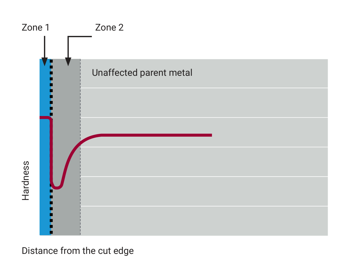
The cutting operation causes a non-uniform heat treatment of the cutting edge and its surroundings. For instance, the peak temperatures in the steel decrease as the distance from the cutting edge increases. This non-uniform thermal heat treatment causes the mechanical properties in the HAZ to vary. Thermal cutting methods always induce tensile stresses in and around the area to be cut. Thermal cutting of Hardox® wear steel will result in a HAZ that can be divided in two zones, a re-quenched and a tempered zone.
The outer part of the HAZ, located approximately 1-2 mm (0.039-0.079”) from the cut edge, has been heated to above 900 °C (1,652 °F) during the cutting procedure. After the cutting torch has passed, the heat rapidly spreads to the plate, cooling the material in zone 1 so rapidly that the material is re-quenched. The hardness, as well as the strength, in this zone is higher than in other parts of the HAZ and the unaffected parent metal.
Zone 2, positioned between zone 1 and the unaffected parent material, is heated to temperatures below 900 °C (1,652 °F) during cutting. The hardness values in this zone vary depending on the steel grade and the cutting performance. The material in this zone is tempered by the heat from the cutting operation.
During cooling, zone 1 strives to expand in the thickness direction, while zone 2 is unaffected, or even shrinks. As a result, residual tensile stresses are created in the thickness direction in zone 2. It is in this zone with high tensile stresses where the hydrogen cracks are initiated. The general tendency is that these stress levels increase with larger plate thicknesses.
Figure 5. Schematic hardness profile of the HAZ due to thermal cutting of Hardox® 450.
Tensile stresses due to the global stress field
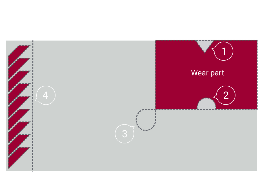
Quenching of wear steel introduces residual stresses. When workpieces with sharp corners are cut, the residual stresses from the manufacturing are concentrated in such areas. These concentrated stresses might be high enough to initiate hydrogen cracks, and therefore sharp corners will increase the risk of cut edge cracking. This is true for thermal and cold cutting methods like AWJ cutting. Considering the following actions will lower the risk of cracks:
- If possible, avoid sharp inward-facing corners.
- If possible, use smooth geometries.
- When sharp corners can’t be avoided, make circular loops around outward-facing corners, when possible.
- If the cutting operation must be stopped (i.e. overnight), make a clean cut to remove stress raisers.
With the exception of Hardox® HiTuf and Hardox® HiTemp, all Hardox® grades are sensitive to cut edge cracking at sharp geometries.
Figure 6. An appropriate procedure for cutting of corners. Take into account that the cutting speed is typically reduced at the cross section, where the cutting path intersects, in order to attain a stable cutting operation.
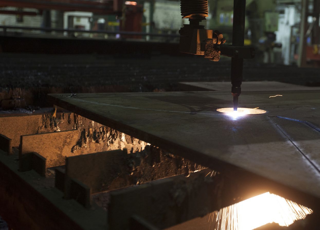
Measures to avoid hydrogen cracking
To avoid cut edge cracking, it is important to keep both the hydrogen content and the tensile stresses in the HAZ as low as possible. The following actions can be used to minimize the hydrogen content as well as the residual stresses in the HAZ.
- Preheating the plate
- Postheating
- Reduced cutting speed (oxy-fuel)
- A combination of preheating, postheating and reduced cutting speed, together with a prolonged cooling process of the HAZ
Hydrogen
Cutting cracks are closely associated with hydrogen. These cutting cracks occur with a time delay after cutting. As long as the plate is hot, about 200 °C (392 °F), it will not crack. When the temperature drops below 200 °C (392 °F), the cracks can occur with a time delay. If cracks do occur, they will occur several hours after cutting, and the process of crack formation will normally be completed after two days. The crack initiation can, in the worst case, take several weeks.
The hydrogen is dissolved in the steel plate. The lower the hydrogen content, the less crack-sensitive the steel plate is. If the plate was free of hydrogen, no cutting cracks would occur. Exactly how hydrogen causes cutting cracks remains a mystery to this day.
By cutting at elevated working temperature, the cut edge will be hot for a relatively long time after cutting. The hotter the steel, the faster the hydrogen diffuses out of the cut. At temperatures below about 100 °C (212 °F), the hydrogen diffusion is so slow that it has no significance. If the steel remains above 100 °C (212 °F) for many hours, the hydrogen will be expelled from the cut and reduces the risk of cracking.
Preheating
One method of avoiding hydrogen cracking when cutting is to preheat the material. The heat will allow more hydrogen to diffuse away from the cut edge, and it will reduce the cooling speed of the cut edge, which reduces the introduced tensile stresses.
Preheating can preferably be used prior to oxy-fuel cutting and plasma cutting with oxygen as plasma gas. Regarding all types of laser cutting and plasma cutting with nitrogen, preheating is not recommended due to its negative effect on the cut edge quality.
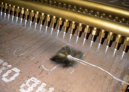
Depending on the situation, either part of the plate or the entire plate can be heated. The most common ways to preheat the plate are:
- Heating furnace
- Preheating lances
- Electrical mats
Heating in furnaces is the best way to preheat the plate, since it gives an even temperature for the entire plate. Preheating lances can also be applied for preheating Hardox® wear plate. It is important that the lances are in motion, so that the temperature of the wear plate does not exceed the maximum preheating temperature.
Further, the preheating temperature is measured on the opposite side of where the preheating is applied. Electrical mats are a slow preheating method, so a good practice for preheating to 150-200 °C (302-392 °F) is to preheat overnight and begin the cutting operation the next morning.
Figure 7. Preheating lances.
Table 6. Preheat temperatures for oxy-fuel cutting of the Hardox® grades. The maximum preheating temperature applies to every thickness band of its grade.
Grade | Plate thickness, mm (in.) | Minimum preheating temperature, °C (°F) | Maximum preheating temperature, °C (°F) |
|---|---|---|---|
Hardox® HiAce | < 40 (< 1.575) | No preheating | 225 (437) |
Hardox® HiAce | 40–49.9 (1.575–1.965) | 100 (212) | 225 (437) |
Hardox® HiAce | 50–69.9 (1.969–2.752) | 150 (302) | 225 (437) |
Hardox® HiAce | ≥ 70 (≥ 2.756) | 175 (347) | 225 (437) |
Hardox® HiTemp | 5–51 (0.197–2.008) | No preheating | 500 (932) |
Hardox® HiTuf | < 90 (< 3.543) | No preheating | 300 (572) |
Hardox® HiTuf | ≥ 90 (≥ 3.543) | 100 (212) | 300 (572) |
Hardox® 400 | < 45 (< 1.772) | No preheating | 225 (437) |
Hardox® 400 | 45–59.9 (1.772–2.358) | 100 (212) | 225 (437) |
Hardox® 400 | 60–80 (2.362–3.150) | 150 (302) | 225 (437) |
Hardox® 400 | > 80 (> 3.150) | 175 (347) | 225 (437) |
Hardox® 450 | < 40 (< 1.575) | No preheating | 225 (437) |
Hardox® 450 | 40–49.9 (1.575–1.965) | 100 (212) | 225 (437) |
Hardox® 450 | 50–69.9 (1.969–2.752) | 150 (302) | 225 (437) |
Hardox® 450 | ≥ 70 (≥ 2.756) | 175 (347) | 225 (437) |
Hardox® 500 Tuf | ≤ 38.1 (1.5) | No preheating | 180 (356) |
Hardox® 500 | < 25 (< 0.984) | No preheating | 225 (437) |
Hardox® 500 | 25–49.9 (0.984–1.965) | 100 (212) | 225 (437) |
Hardox® 500 | 50–59.9 (1.969–2.358) | 150 (302) | 225 (437) |
Hardox® 500 | ≥ 60 (≥ 2.362) | 175 (347) | 225 (437) |
Hardox® 550 | < 20 (< 0.787) | No preheating | 200 (392) |
Hardox® 550 | 20–51 (0.787–2.008) | 150 (302) | 200 (392) |
Hardox® 550 | > 51 (> 2.008) | 175 (347) | 200 (392) |
Hardox® 600 | < 12 (< 0.472) | No preheating | 180 (356) |
Hardox® 600 | 12–65 (0.472–2.559) | 170 (338) | 180 (356) |
Hardox® Extreme* | 8–19 (0.315–0.748) | 100 (212) | 100 (212) |
*SSAB recommends AWJ cutting for Hardox® Extreme. If only oxy-fuel cutting is available, follow the recommendations in Table 6.
Postheating
Postheating is a reliable method for avoiding cut edge cracking. It can be done in either a furnace or with torches. It is important that the postheating process takes place as soon as possible after the piece has been cut out. The time between the start of the cutting procedure and the start of the postheating procedure should be as short as possible, and never exceed 60 minutes.
When using furnaces, the temperature should not exceed the maximum allowable temperature listed in Table 6 and the plate has to stay in the furnace until it reaches this temperature. Depending on the thickness of the plate, the holding time will vary; as a general rule of thumb the duration of postheating should be at least 5 minutes for every mm of plate thickness (i.e. 50 minutes for a 10 mm (0.394”) thick plate). Postheating in a furnace will allow more hydrogen migration from the HAZ, as well as a small reduction of tensile stresses in the HAZ.
When using torches, it is important not to overheat. The temperature of the cut edge should not exceed 700 °C (1,292 °F), preferentially 300 to 500 °C (572-932 °F). Normally post-heat treatment using torches is done manually, and in this case it is important to know how to control the temperature. This is done by looking at the color of the cut edge at the torch; it should just start to glow (very dark red). If the color is bright cherry red or dark orange the temperature is too high and the postheating will not be successful.
It is also possible to control the temperature with an infrared thermometer, pointed directly to the cut edge at the flame.
The heat from the torch will temper the re-quenched zone of the HAZ, which will reduce the tensile stresses at the cut edge. The torch used should have a rather big flame with low intensity. This will allow the heat to reach further into the material without heating it too much.
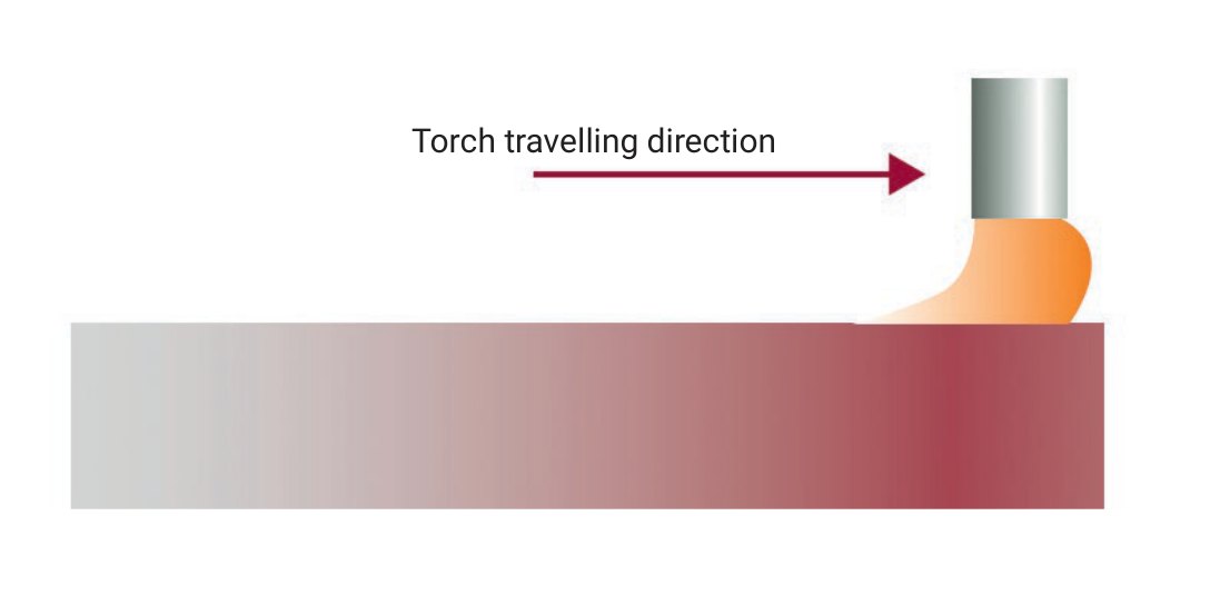
Figure 8. Color of the cut edge behind the postheating torch, in the torch’s travelling direction.
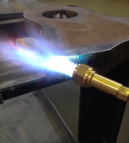
Figure 9. Manual postheating.
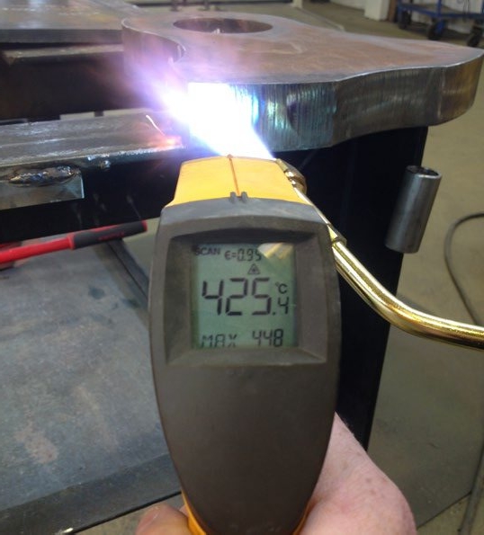
Figure 10. Temperature measurement during postheating.
Reduced cutting speed
Reduced cutting speed is a convenient method for reducing the risk of cracks during oxy-fuel cutting. When the cutting speed is reduced, the material heats up around the cut front, and the heat affected zone will be wider. This affects the residual stresses in such a way that reduces the risk of cut edge cracking. Bear in mind, though, that reduced cutting speed is not as reliable as preheating or postheating, and should only be used as a substitute if, for instance, the workshop does not have appropriate pre- or post-heating equipment.
SSAB strongly recommends using preheating instead of reduced cutting speed. SSAB does not guarantee that a crack will not appear by cutting with reduced cutting speed; however, the risk for such cracks will be reduced when compared with normal speed cutting in cold plates.
If reduced cutting speed is used, it is important that the cutting speed does not exceed the one listed in Table 7. Otherwise the risk for cutting cracks won’t be reduced at all.
Do not use a nozzle that is too big. So, use a 25-50 mm (1-2”) nozzle instead of a 50-100 mm (2-4”) nozzle for a 50 mm (1.969”) thick Hardox® plate. To get a good cut edge quality, the cutting oxygen pressure needs to be reduced. The amount of pressure needed depends on type and size of the nozzle. Always do a test cut and adjust the cutting oxygen pressure until a good cut edge quality is obtained.
Make sure that the Hardox® steel plate is as warm as possible prior to cutting. For example, during winter, store the plate inside the workshop some time prior to cutting. Reduced cutting speed is not applicable for plasma cutting.
Table 7. Maximal cutting speed in mm/min for oxy-fuel cutting without preheating. A blank cell means the grade is not supplied in that thickness.
Max plate thickness, mm (in.) | Hardox® HiTemp | Hardox® HiTuf | Hardox® 400 | Hardox® 450 | Hardox® 500 | Hardox® 550 | Hardox® 600 | Hardox® Extreme |
|---|---|---|---|---|---|---|---|---|
12 (0.472) | no restriction | no restriction | no restriction | no restriction | no restriction | no restriction | no restriction | ** |
15 (0.591) | no restriction | no restriction | no restriction | no restriction | no restriction | no restriction | 300 | ** |
20 (0.787) | no restriction | no restriction | no restriction | no restriction | no restriction | no restriction | 200 | ** |
25 (0.984) | no restriction | no restriction | no restriction | no restriction | 300 | 270 | 180 | |
30 (1.181) | no restriction | no restriction | no restriction | no restriction | 250 | 230 | 150 | |
35 (1.378) | no restriction | no restriction | no restriction | no restriction | 230 | 190 | 140 | |
40 (1.575) | no restriction | no restriction | no restriction | 230 | 200 | 160 | 130 | |
45 (1.772) | no restriction | 230 | 230 | 200 | 170 | 140 | 120 | |
50 (1.969) | no restriction | 210 | 210 | 180 | 150 | 130 | 110 | |
60 (2.362) | 200 | 200 | 170 | 140 | * | * | ||
70 (2.756) | 190 | 190 | 160 | 135 | * | * | ||
80 (3.150) | 180 | 180 | 150 | 130 | ||||
> 80 (3.150) | * | * | * | * |
*Only preheating is applicable. **SSAB recommends AWJ cutting. Slow cutting by itself is not a sufficient method for counteracting cutting cracks in Hardox® Extreme; if the only available method is oxy-fuel cutting, use preheating together with postheating with a torch.
Slow cooling
Regardless of whether or not the cut parts are preheated, a slow cooling rate will reduce the risk of cut edge cracking. Slow cooling can be achieved if the parts are stacked together while still warm from the cutting process, and are covered with an insulating blanket. Allow the parts to slowly cool down to room temperature.
Softening
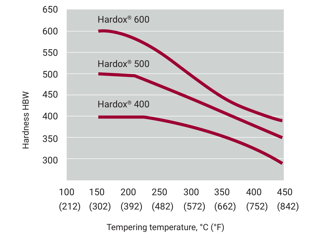
The resistance of the steel to softening depends on its chemistry, microstructure and how it was processed. The smaller the piece that is thermally cut, the greater the risk of the whole component being softened. If the temperature of the steel becomes too high, the hardness of the steel will be reduced. Check the maximum allowable temperature in Table 6.
Figure 11. Surface hardness against tempering temperature for Hardox® 400, Hardox® 500 and Hardox® 600.
Reducing the risk of softening — cutting method
When small parts are cut, the heat supplied by the cutting torch and by preheating will be accumulated in the workpiece. The smaller the size of the cut part, the greater the risk of softening. When oxy-fuel is used for cutting 30 mm (1.181”) or thicker plate, the rule of thumb is: there is a risk of loss of hardness of the entire component if the distance between two cuts is less than 200 mm (7.874”). For thicknesses below 30 mm (1.181”), it is possible to cut smaller parts without loss of hardness. A convenient way to determine if the piece is too small is to measure the temperature of the part directly after it has been cut out. Maximum allowable temperatures can be found in Table 6.
The best way of eliminating the risk of softening is to use cold cutting methods, such as abrasive water jet cutting. If thermal cutting must be performed, laser or plasma cutting is preferable to oxy-fuel cutting. This is because oxy-fuel cutting introduces more heat to the workpiece compared to plasma or laser cutting.
Submerged cutting
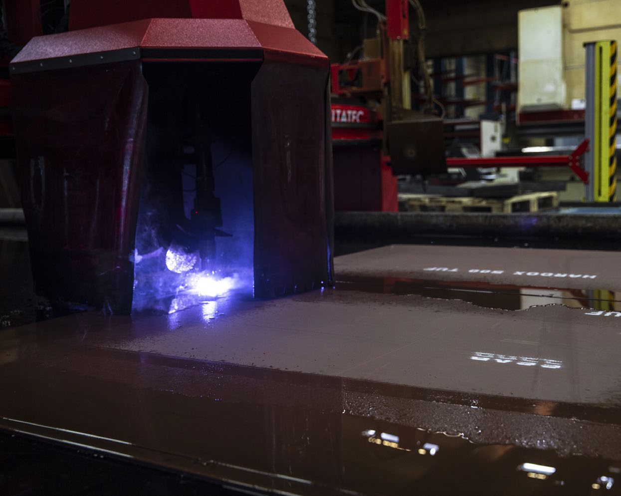
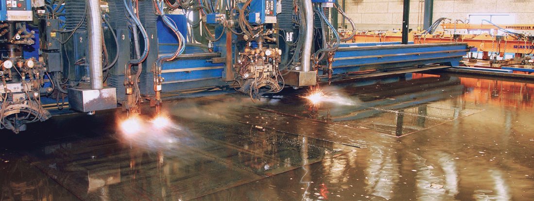
An effective way of limiting and reducing the extent of the soft zone is to water-cool the plate and the cut surface during the cutting operation. This can be done either by submerging the plate in water or by spraying water on the piece during and after cutting.
Even if cutting is done by submersion or spraying water on the piece during and after cutting, a soft zone will still occur in the cutting edge in a distance of approximately 5-10 mm (0.197-0.394”). Any water is pushed away by the ignition flame and the cutting oxygen jet so that the water cannot cool the cutting front. When the water finally arrives, the cutting edge has already softened. On the other hand, water cooling saves the component from “global” softening.
Submerged cutting can be done with both plasma cutting and oxy-fuel cutting. Some advantages of submerged cutting are:
- Prevents loss of hardness of the entire component
- Reduced distortion of the cut piece
- Pieces are cooled directly after cutting
- No fumes or dust
- Reduced noise level
Since preheating is not applicable for submerged cutting, the only available measures to counteract the risk for hydrogen cracking are postheating and reduced cutting speed. When small pieces are cut from thick Hardox® wear plate, using oxy-fuel, there is risk of softening as well as cut edge cracking. This is best avoided through submerged cutting at low cutting speeds, or with a post-heat treatment of the cut pieces. The postheating can be done either with a torch or in a furnace.
Figure 12. Submerged cutting.
Practical tips
Plate handling
Never return a plate to stock with any sharp corners left. These corners will act as stress raisers and may cause delayed cracking in the plate. Always make a clean cut to remove such sharp corners before returning the plate to stock. This is true for all cutting methods, both thermal and cold cutting methods like AWJ cutting. Hardox® 550, Hardox® 600 and Hardox® Extreme are especially sensitive to this.
While storing Hardox® 550, Hardox® 600 and Hardox® Extreme, make sure the steel plates are not subjected to three-point bending. Three-point bending can occur if the plates are stacked with dunnage between the layers and the wood is not properly placed. Always make sure that the wood in each layer is placed on top of the wood in the layer beneath it.
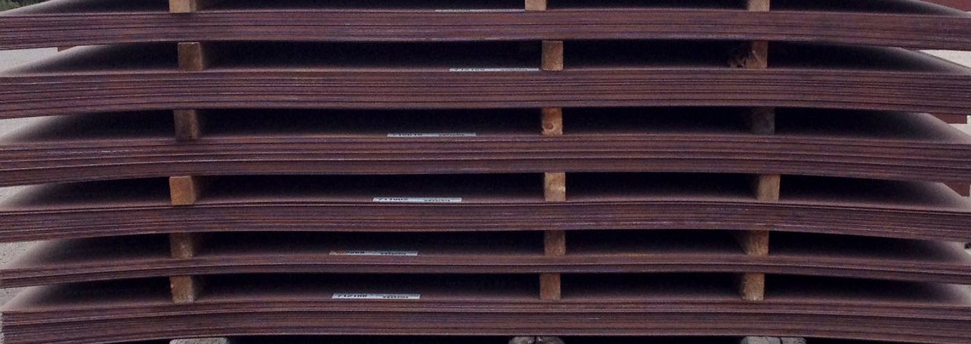
Figure 13a. Properly stacked plates.
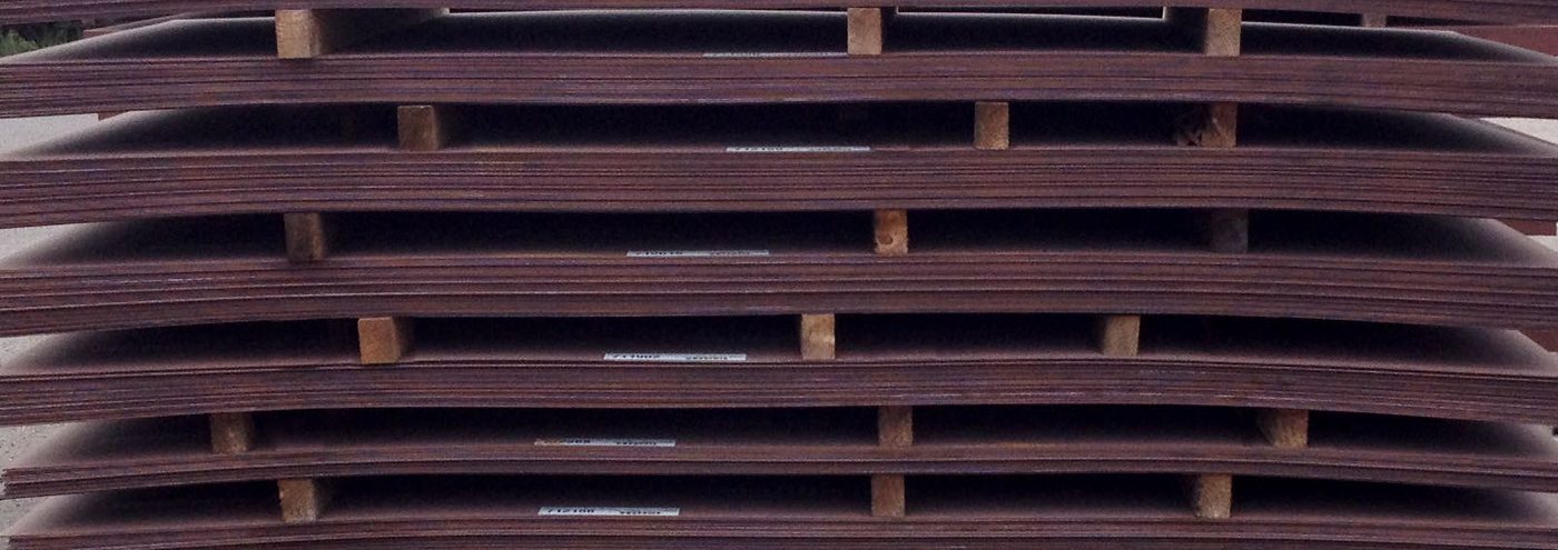
Figure 13b. Improperly stacked plates.
Preheating and postheating
A very simple and inexpensive solution for preheating is to use electrical heating elements and insulation blankets (Rockwool or a similar insulation product).
Improvised solution for preheating
- Place heat protection for the floor (if you have a heat sensitive floor)
- Put plate supports on top (in this case, U-beams)
- Cover it with insulation
- Put on the electric heating pads
- Put on the plate and place thermal couples which will log the temperature over time
- Cover everything with insulation
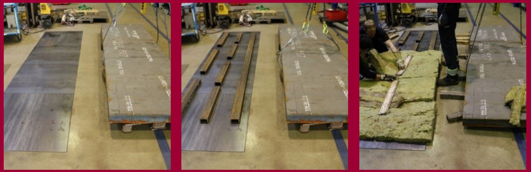
Steps 1–3. Heat protection for the floor, plate supports on top, then covered with insulation.
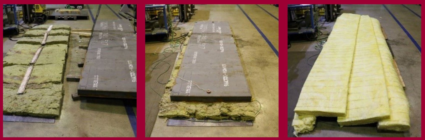
Steps 4–6. Electric heating pads, then the plate with thermal couples, then everything covered with insulation.
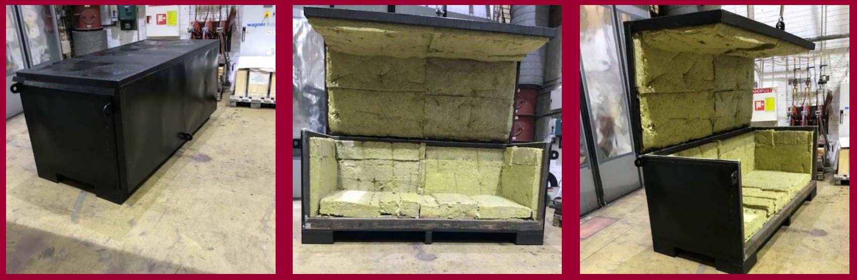
Another inexpensive and practical solution is to build a heat treatment box and use it with electrical heating. This could easily be used for preheating, postheating and slow cooling.
Contact and more information
Contact your local SSAB representative or Tech Support at [email protected], or visit www.hardox.com.
Hardox® is a trademark of the SSAB group of companies. The information contained in this brochure is provided only as general information. It is the user’s responsibility to independently determine suitability of all products and applications, and to test and verify the same.