




Hardox® Bending
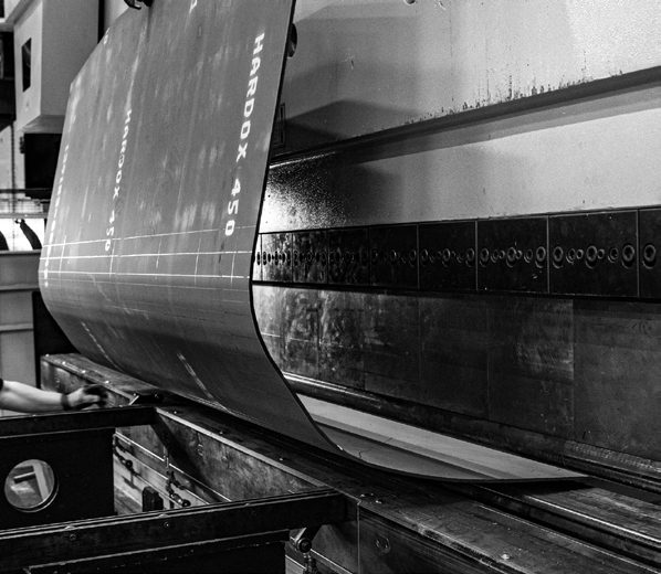
This brochure contains recommendations for bending of Hardox® wear plate. It is intended as a guide, and contains general suggestions for how to achieve the best results when bending.
Bending high-strength steel sheet and plate rarely proves to be difficult. However, there are certain parameters that must be considered.
A highly pure steel with few inclusions is fundamental to achieving a good bending result. SSAB’s modern processing allows for high standards of surface quality, tolerances and mechanical properties.
Preparation before bending
- Check the rolling direction of the plate. If possible, orient the rolling direction transverse to the bend line. The plate can often be bent tighter this way, than with the bend line parallel to the rolling direction. See Figure 1.
- Check the surface quality of the plate. Surface damage can reduce bendability as it can be the cause of fractures. For heavy plates, defects on the plate such as scratches and rust can often be removed with careful grinding. Preferably grind any scratches transverse to the bend line.
- Thermal cut and sheared edges should be deburred and rounded with a grinder.
- Check the condition of the tools.
- To avoid excessive tool wear, tooling should be harder than the workpiece.
- Check that the tools and tool setup are in line with the given recommendations in this brochure.
- The edges of the die opening should always be as hard as or harder than the plate being bent, in order to avoid excessive damage to the die. A simple way of achieving this is to mill grooves in the die edges and fit lubricated round rods of, for example, hardened steel into the grooves. The edge radius of the die should be at least half the plate thickness.
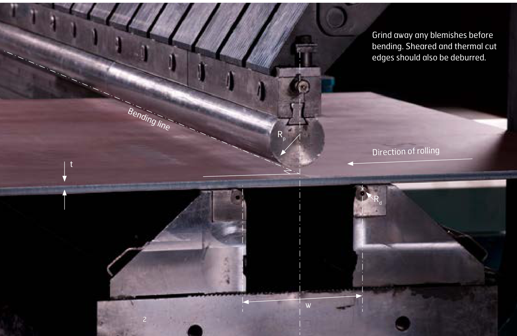
Figure 1. Bending transverse to the direction of rolling. Grind away any blemishes before bending; sheared and thermal cut edges should also be deburred.
To consider
- Always take safety precautions and follow local safety regulations. Only qualified people may be by or in the vicinity of the machine. When high-strength steel is being bent, nobody should stand in front of the press brake.
- Check that the punch together with the workpiece do not bottom out in the die.
- Consider springback. Avoid rebending to correct the profile angle. The exposure of a material to previous forming processes reduces its bendability to a great extent.
- Bending force, springback and, in general, minimum recommended punch radius increase with the strength of the steel.
- In many Hardox® plates, the identity of the plate is stamped perpendicular to the rolling direction. Avoid placing the bending line over the stamp due to the risk of cracking.
- Excessive blast cleaning can have a negative effect on bendability. Recommendations for Hardox® wear plate are based on tests with blast cleaned and primed surfaces.
- High strain rate may cause a local temperature increase in the bend. This could have an adverse impact on the bendability, especially for thicknesses above 20 mm (0.787”). If possible, reduce the punch speed to decrease the temperature difference within the workpiece.
Tools
Die width
Springback increases with increased die width, while bending force is reduced. Make sure that the opening angle of the die allows for over-bending, without bottoming out, to compensate for springback. An increased die opening width can in many cases lower the strain level in the bend. Also, make sure that there is enough room for the chosen punch together with the workpiece in the die during bending, without deforming the die. The minimum recommended die opening widths are shown in tables 2 and 3.
The die edge radius should be at least half the plate thickness. Alternatively, the die width should be increased in order to minimize pressure on the die edge radius, and consequently reduce the risk of die marks.
Punch
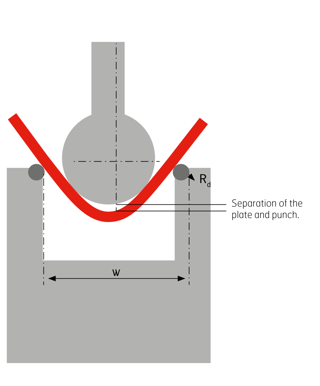
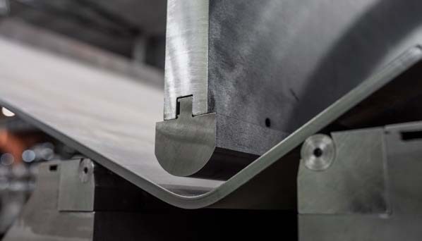
The suitable punch radius, along with the die width, is the most important parameter. When bending high-strength steel, the final inner radius often becomes somewhat smaller than the radius of the punch, Figure 2. When there is low friction between plate and tools, the phenomenon becomes more obvious.
Figure 2. Separation of the plate during bending.
Condition of tools
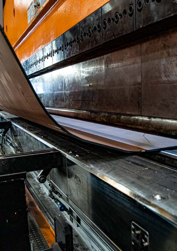
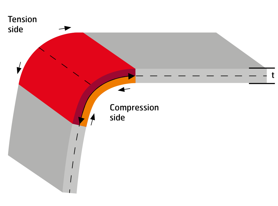
Due to the increased contact pressure between plate and tools when bending high strength Hardox® wear steel, wear on the tools increases somewhat. Check regularly that the punch radius and die edge radius are both constant. For bends that have cracked in a workpiece, the crack has in many cases propagated from the compression side of the bend, Figure 3. This can often be attributed to poor punch condition. The edges of the die should remain clean and undamaged.
Machine stability
Required bending force is often high when bending high-strength steel. The static friction coefficient is typically higher than the kinetic. This can cause the plate to lock over the edge of one die edge radius, and at the same time slide over the other one. In this way, the workpiece swings down into the die in a discontinuous way during the bending process. This phenomenon, called stick-slip, can result in higher strains over the bend. Use a stable machine and steady tool fastening. Lubrication of the die edge or use of a rotating die edge radius can be helpful, avoiding stick-slip and also lowering the bending force.
Figure 3. Bend, showing the tension side and the compression side.
Crowning
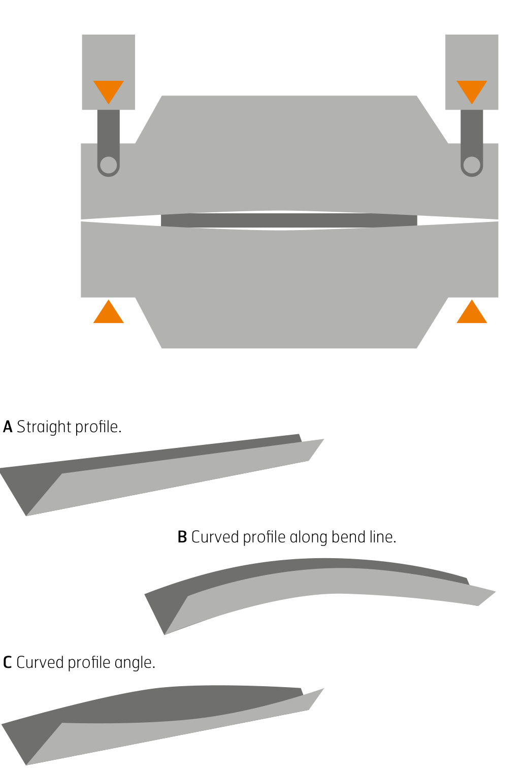
Crowning compensates for the elastic deflection of the bending machine under load, Figure 4. The central part of punch and die deflects the most. By crowning, the deflection (C) can be compensated for, thus achieving the same bending angle along the entire blank length. If the bend profile becomes curved along the bend line (B) this cannot be compensated for by crowning.
After unloading, compressive stresses arise on the stretched side, at the same time as tensile stresses appear on the compressed side, Figure 3. The stress distribution over the plate thickness causes longitudinal stresses. It is those stresses that tend to curve the profile. The magnitude of curvature depends mainly on the flange height and the profile stiffness.
Additional considerations have to be made when setting the crowning at stepwise bending of long profiles.
Figure 4. Crowning. A straight profile, B curved profile along bend line, C curved profile angle.
Bending force
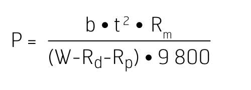
To make an estimation of the force needed during bending, consider not only the bend length, plate thickness, die width and tensile strength, but also the changing moment arm during bending. The peak load is assumed to be reached at a bend opening angle of 120° with normal friction (no lubrication). Trial tests are always recommended.
- P = Bend force, tons (metric)
- t = Plate thickness, mm
- W = Die width, mm (figure 1)
- b = Bend length, mm
- Rm = Tensile strength, MPa (table 1)
- Rd = Die entry radius, mm
- Rp = Punch radius, mm
The SSAB Bending Formula© is verified in tests for 90° bends.
Table 1. Typical tensile strength values to calculate bend force. These values are not to be used for design or acceptance testing.
Hardox® grade | Typical tensile strength (MPa) |
|---|---|
Hardox® 400 | 1250 |
Hardox® 450 | 1400 |
Hardox® 500 Tuf | 1600 |
Hardox® 500 | 1650 |
Hardox® HiAce | 1400 |
Hardox® HiTemp | 1250 |
SSAB BendCalc
Please consider the SSAB BendCalc app to get the correct bending settings for Hardox® wear steel. The first software to predict springback and punch depth!
Based on the steel characteristics, die and tool symmetry, final bend shape and friction conditions, it gives you the result in seconds:
- Maximum bend force
- Springback
- Punch depth
- Opening angle during maximal stroke
- Minimum flange height
You can save the results and share the report as a PDF.
Springback
Springback increases with steel strength and the ratio between die width and plate thickness (W/t). Material yield strength has the biggest influence. When bending, a varying residual stress distribution is achieved over the bend cross section. The plastic strain level and the distribution of these stresses will control the tendency for springback. All springback is fully elastic.
To compensate for springback, the die should be shaped in such a way to allow overbending without coining the material. It is very difficult to accurately predict the springback of a material when bending, since this depends to a large extent on each unique tool setup. That is why trials are recommended.
For thinner plate or sheet (t < 10 mm (0.394”)), you can estimate the material’s springback, in degrees, by dividing the tensile strength (MPa) by 100 (see Table 1 for the typical tensile strength of Hardox® steel grades). A precondition is that the die width is approximately 10–12 x the plate thickness.
Parameters that affect springback
- Yield strength of the material – higher yield strength causes greater springback.
- Punch radius – increased punch radius will cause greater springback.
- Die width – larger die width causes greater springback.
- The strain hardening of the material.
Bending recommendations
Bend tests and their evaluation vary somewhat. For Hardox® plate products the minimum recommended relationship between the punch radius and plate/sheet thickness (R/t) is shown in Table 2, and corresponding recommendations for sheets are presented in Table 3. These bend recommendations are based on bend tests of one step to 90° after unloading. Die opening widths are guidelines and may vary somewhat without affecting bending results.
Hardox® wear plate is delivered with guaranteed bending performance according to Hardox® guarantees.
For more technical information, please contact Tech Support or visit www.ssab.com. You can also contact your local SSAB representative.
Table 2. Hardox® wear plate, bending recommendations in mm. Based on dies with rolls and normal friction (no lubrication). R/t stands for punch radius (R) divided by sheet thickness (t).
Hardox® grade | Thickness range in mm | Transverse to rolling direction minimum Rp/t | Along rolling direction minimum Rp/t | Die opening width (W) minimum W/t |
|---|---|---|---|---|
Hardox® 400 | t < 8 | 2.5 | 3.0 | 12 |
Hardox® 400 | 8 ≤ t < 20 | 3.0 | 4.0 | 14 |
Hardox® 400 | 20 ≤ t < 50 | 4.0 | 5.0 | 16 |
Hardox® 450 | t < 8 | 3.0 | 3.5 | 12 |
Hardox® 450 | 8 ≤ t < 20 | 3.5 | 4.5 | 14 |
Hardox® 450 | t ≥ 20 | 4.5 | 5.0 | 16 |
Hardox® 500 Tuf | t < 8 | 3.0 | 3.5 | 12 |
Hardox® 500 Tuf | 8 ≤ t < 20 | 3.5 | 4.5 | 14 |
Hardox® 500 Tuf | t ≥ 20 | 4.5 | 5.0 | 16 |
Hardox® 500 | t < 8 | 3.5 | 4.5 | 12 |
Hardox® 500 | 8 ≤ t < 15 | 4.0 | 4.5 | 14 |
Hardox® 500 | 15 ≤ t < 20 | 4.5 | 5.0 | 14 |
Hardox® 500 | t ≥ 20 | 5.5 | 6.0 | 16 |
Hardox® 550 | 8 ≤ t < 65 | Please contact SSAB Tech Support | ||
Hardox® 600 | 6 ≤ t < 65 | Please contact SSAB Tech Support | ||
Hardox® HiAce | t < 8 | 3.0 | 3.5 | 12 |
Hardox® HiAce | 8 ≤ t < 20 | 3.5 | 4.5 | 14 |
Hardox® HiAce | t ≥ 20 | 4.5 | 5.0 | 16 |
Hardox® HiTemp | t < 8 | 3.0 | 3.5 | 12 |
Hardox® HiTemp | 8 ≤ t < 20 | 3.5 | 4.5 | 14 |
Hardox® HiTemp | t ≥ 20 | 4.5 | 5.0 | 16 |
Table 2b. Hardox® wear plate, bending recommendations in inches.
Hardox® grade | Thickness range in inches | Transverse to rolling direction minimum Rp/t | Along rolling direction minimum Rp/t | Die opening width (W) minimum W/t |
|---|---|---|---|---|
Hardox® 400 | t < 0.315” | 2.5 | 3.0 | 12 |
Hardox® 400 | 0.315” ≤ t < 0.787” | 3.0 | 4.0 | 14 |
Hardox® 400 | 0.787” ≤ t < 1.969” | 4.0 | 5.0 | 16 |
Hardox® 450 | t < 0.315” | 3.0 | 3.5 | 12 |
Hardox® 450 | 0.315” ≤ t < 0.787” | 3.5 | 4.5 | 14 |
Hardox® 450 | t ≥ 0.787” | 4.5 | 5.0 | 16 |
Hardox® 500 Tuf | t < 0.315” | 3.0 | 3.5 | 12 |
Hardox® 500 Tuf | 0.315” ≤ t < 0.787” | 3.5 | 4.5 | 14 |
Hardox® 500 Tuf | t ≥ 0.787” | 4.5 | 5.0 | 16 |
Hardox® 500 | t < 0.315” | 3.5 | 4.5 | 12 |
Hardox® 500 | 0.315” ≤ t < 0.591” | 4.0 | 4.5 | 14 |
Hardox® 500 | 0.591” ≤ t < 0.787” | 4.5 | 5.0 | 14 |
Hardox® 500 | t ≥ 0.787” | 5.5 | 6.0 | 16 |
Hardox® 550 | 0.315” ≤ t < 2.560” | Please contact SSAB Tech Support | ||
Hardox® 600 | 0.236” ≤ t < 2.560” | Please contact SSAB Tech Support | ||
Hardox® HiAce | t < 0.315” | 3.0 | 3.5 | 12 |
Hardox® HiAce | 0.315” ≤ t < 0.787” | 3.5 | 4.5 | 14 |
Hardox® HiAce | t ≥ 0.787” | 4.5 | 5.0 | 16 |
Hardox® HiTemp | t < 0.315” | 3.0 | 3.5 | 12 |
Hardox® HiTemp | 0.315” ≤ t < 0.787” | 3.5 | 4.5 | 14 |
Hardox® HiTemp | t ≥ 0.787” | 4.5 | 5.0 | 16 |
Table 3. Hardox® wear sheet, bending recommendations in mm. Based on dies with rolls and normal friction (no lubrication).
Hardox® grade | Thickness range in mm | Transverse to rolling direction minimum Rp/t | Along rolling direction minimum Rp/t | Die opening width (W) minimum W/t |
|---|---|---|---|---|
Hardox® 400 | 2 ≤ t < 4 | 3.0 | 4.0 | 12 |
Hardox® 400 | 4 ≤ t ≤ 8 | 3.0 | 3.5 | 12 |
Hardox® 450 | 2 ≤ t < 4 | 3.0 | 4.0 | 12 |
Hardox® 450 | 4 ≤ t ≤ 8 | 3.0 | 3.5 | 12 |
Hardox® 450 CR | 0.8 ≤ t ≤ 2.1 | 4.0 | 4.0 | 12 |
Hardox® 500 Tuf | 3 ≤ t < 4 | 3.0 | 4.0 | 12 |
Hardox® 500 Tuf | 4 ≤ t ≤ 6.4 | 3.0 | 3.5 | 12 |
Hardox® 500 | 2 ≤ t ≤ 7 | 3.5 | 4.0 | 12 |
Hardox® 600 | 3 ≤ t ≤ 6 | Please contact SSAB Tech Support | ||
Table 3b. Hardox® wear sheet, bending recommendations in inches.
Hardox® grade | Thickness range in inches | Transverse to rolling direction minimum Rp/t | Along rolling direction minimum Rp/t | Die opening width (W) minimum W/t |
|---|---|---|---|---|
Hardox® 400 | 0.079” ≤ t < 0.157” | 3.0 | 4.0 | 12 |
Hardox® 400 | 0.157” ≤ t ≤ 0.315” | 3.0 | 3.5 | 12 |
Hardox® 450 | 0.079” ≤ t < 0.157” | 3.0 | 4.0 | 12 |
Hardox® 450 | 0.157” ≤ t ≤ 0.315” | 3.0 | 3.5 | 12 |
Hardox® 450 CR | 0.031” ≤ t ≤ 0.083” | 4.0 | 4.0 | 12 |
Hardox® 500 Tuf | 0.118” ≤ t < 0.157” | 3.0 | 4.0 | 12 |
Hardox® 500 Tuf | 0.157” ≤ t ≤ 0.252” | 3.0 | 3.5 | 12 |
Hardox® 500 | 0.079” ≤ t ≤ 0.276” | 3.5 | 4.0 | 12 |
Hardox® 600 | 0.118” ≤ t ≤ 0.236” | Please contact SSAB Tech Support | ||
Contact and more information
Contact your local SSAB representative or Tech Support, or visit hardox.com.
Hardox® is a trademark of the SSAB group of companies. The information contained in this brochure is provided only as general information. It is the user’s responsibility to independently determine suitability of all products and applications, and to test and verify the same.